Seattle – [23 Jun 2021] – CloudIQ Technologies Inc today announced it has earned the Kubernetes on Microsoft Azure advanced specialization, a validation of a solution partner’s deep knowledge, extensive experience and proven expertise in deploying and managing production workloads in the cloud using containers and managing hosted Kubernetes environments in Microsoft Azure.
Only partners that meet stringent criteria around customer success and staff skilling, as well as pass a third-party audit of their container-based workload deployment and management practices, are able to earn the Kubernetes on Azure advanced specialization.
With over 75% of global organizations expected to run containerized applications in production by 2022, many are looking for a partner with advanced skills to migrate their existing containerized workloads to the cloud, or assist them in developing cloud-native applications using container technologies, DevOps patterns, and a microservices approach.
“With our deep expertise in cloud-native architecture design, we help clients build and run scalable applications with improved security, faster release cycles, easier management, and lower costs”, said Mr. Prem Kandalu, CEO. “As a partner who has earned the Kubernetes on Microsoft Azure advanced specialization, CloudIQ will pass on the benefits of our continued collaboration with Microsoft to our clients.”
Rodney Clark, Corporate Vice President, Global Partner Solutions, Channel Sales and Channel Chief at Microsoft added, “The Kubernetes on Microsoft Azure advanced specialization highlights the partners who can be viewed as most capable when it comes to deploying and managing containerized applications in Azure. CloudIQ Technologies clearly demonstrated that they have both the skills and the experience to deliver best-in-class cloud-native capabilities to customers with Azure.
About CloudIQ Technologies
CloudIQ is a leading cloud consulting and solutions firm that helps businesses envision new products, create innovative business models, and deliver the next level of customer experiences by leveraging the cloud. From standalone cloud projects to enterprise-wide cloud architecture design you can rely on our cloud engineering expertise.
As a Microsoft Gold Partner (Cloud Platform), earner of the Modernization of Web Applications on Microsoft Azure and Kubernetes on Microsoft Azure advanced specializations, Kubernetes Certified Service Provider (KCSP) and Kubernetes Training Partner (KTP), we serve as trusted advisors to Fortune 500 organizations and leverage our deep industry expertise in building cloud-native solutions to help our clients realize the cost, scale and security benefits of the cloud.
Amazon Web Services (AWS) is a secure cloud services platform, offering compute power, database storage, content delivery, and other functionalities to help businesses scale and grow.
It gives organizations a secure and robust platform to develop their custom cloud-based solutions and has several unique features that make it one of the most reliable and flexible cloud platform such as
Mobile-friendly access through AWS Mobile Hub
and AWS Mobile SDK
Fully managed purpose-built Databases
Serverless cloud functions
Range of storage options that are affordable and
scalable.
Unbeatable security and compliance
Following are some core services offered by AWS:
AWS Core services
An EC2 instance is a virtual server in Amazon’s Elastic Compute Cloud (EC2) for
running applications on the AWS infrastructure.
Amazon Elastic Block Store (EBS) is a cloud-based block storage system provided by AWS that is
best used for storing persistent data.
Amazon Virtual Private Cloud (Amazon VPC) enables us to launch AWS resources
into a virtual network that we have defined. This virtual network closely
resembles a traditional network that we would operate in our own data center,
with the benefits of using the scalable infrastructure of AWS.
Amazon S3 or Amazon Simple Storage Service is a service offered by Amazon Web Services
that provides object storage through a web service interface. Amazon S3 uses
the same scalable storage infrastructure that Amazon.com uses to run its global
e-commerce network.
AWS security
groups (SGs) are associated with EC2 instances and provide security at the
protocol and port access level. Each security group — working much the same way
as a firewall — contains a set of rules that filter traffic coming into and out
of an EC2 instance.
Let us look more deeply at one of AWS’s core services – AWS CloudFormation – that is key for managing workloads on AWS.
1. CloudFormation
AWS CloudFormation is a service that helps us model and set up our Amazon Web Services resources so that we can spend less time managing those resources and more time focusing on our applications that run in AWS. We create a template that describes all the AWS resources that we want (like Amazon EC2 instances or S3 buckets), and AWS CloudFormation takes care of provisioning and configuring those resources for us. We don’t need to individually create and configure AWS resources and figure out what’s dependent on what; AWS CloudFormation handles all of that.
A stack is a collection of AWS resources that you can manage as a single unit. In other words, we can create, update, or delete a collection of resources by creating, updating, or deleting stacks. All the resources in a stack are defined by the stack’s AWS CloudFormation template.
2. CloudFormation template
CloudFormation templates can be written in either JSON or YAML. The structure of the template in YAML is given below:
---
AWSTemplateFormatVersion: "version date"

Description:
  String
Metadata:
  template metadata
Parameters:
  set of parameters
Mappings:
  set of mappings
Conditions:
  set of conditions
Resources:
  set of resources
Outputs:
  set of outputs
In the above yaml file,
AWSTemplateFormatVersion – The AWS
CloudFormation template version that the template conforms to.
Description – A text string that
describes the template.
Metadata – Objects that provide
additional information about the template.
Parameters – Values to pass to our
template at runtime (when we create or update a stack). We can refer to
parameters from the Resources and Outputs sections of the template.
Mappings – A mapping of keys and
associated values that we can use to specify conditional parameter values, like
a lookup table. We can match a key to a corresponding value by using the
Fn::FindInMap intrinsic function in the Resources and Outputs sections.
Conditions – Conditions that control
whether certain resources are created or whether certain resource properties
are assigned a value during stack creation or update. For example, we can
conditionally create a resource that depends on whether the stack is for a
production or test environment.
Resources – Specifies the stack resources
and their properties, such as an Amazon Elastic Compute Cloud instance or an
Amazon Simple Storage Service bucket. We
can refer to resources in the Resources and Outputs sections of the template.
Outputs – Describes the values that are
returned whenever we view our stack’s properties. For example, we can declare
an output for an S3 bucket name and then call the AWS cloudformation
describe-stacks AWS CLI command to view the name.
Resources is the only required section in the CloudFormation template. All other sections are optional.
3. CloudFormation template to create S3 bucket
S3template.yml
Resources:
  HelloBucket:
    Type: AWS::S3::Bucket
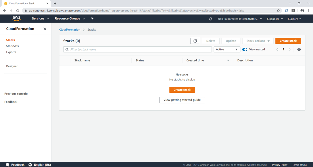
In AWS Console, go to CloudFormation and click on Create Stack
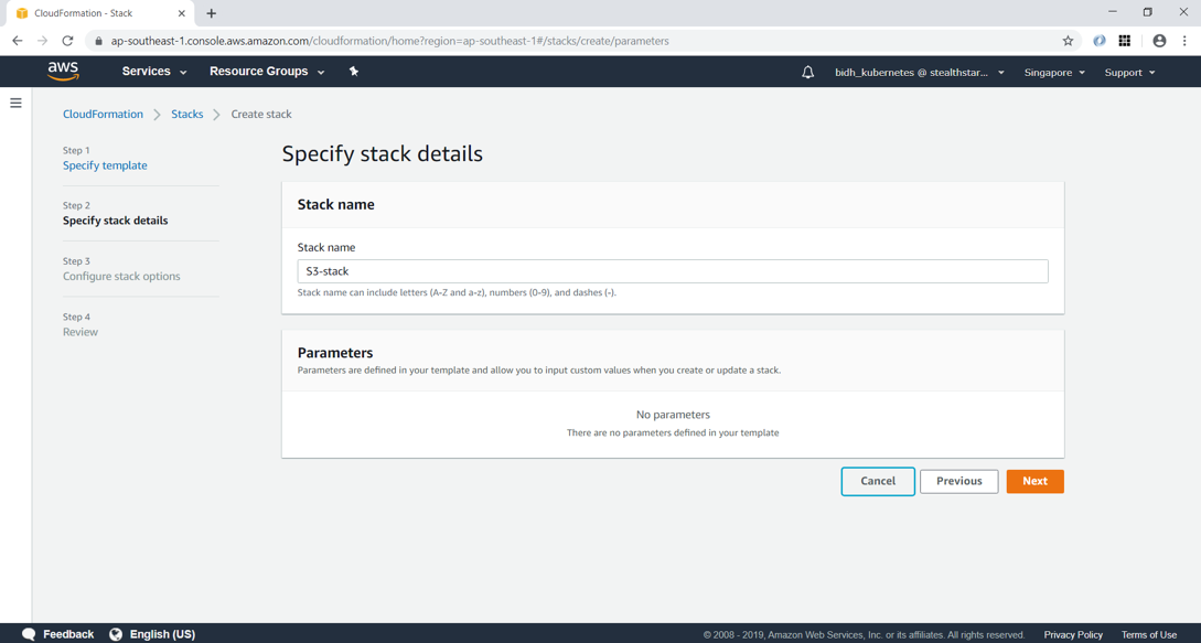
Upload the template file which we created. This will get stored in an S3 location, as shown below.
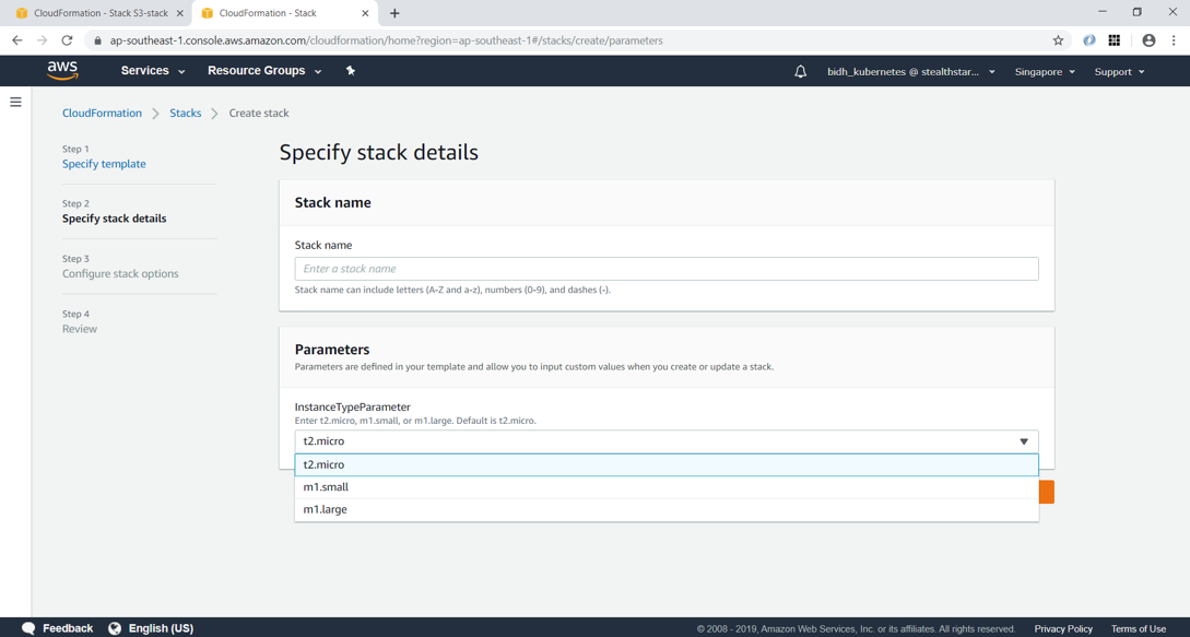
Click next and give a stack name
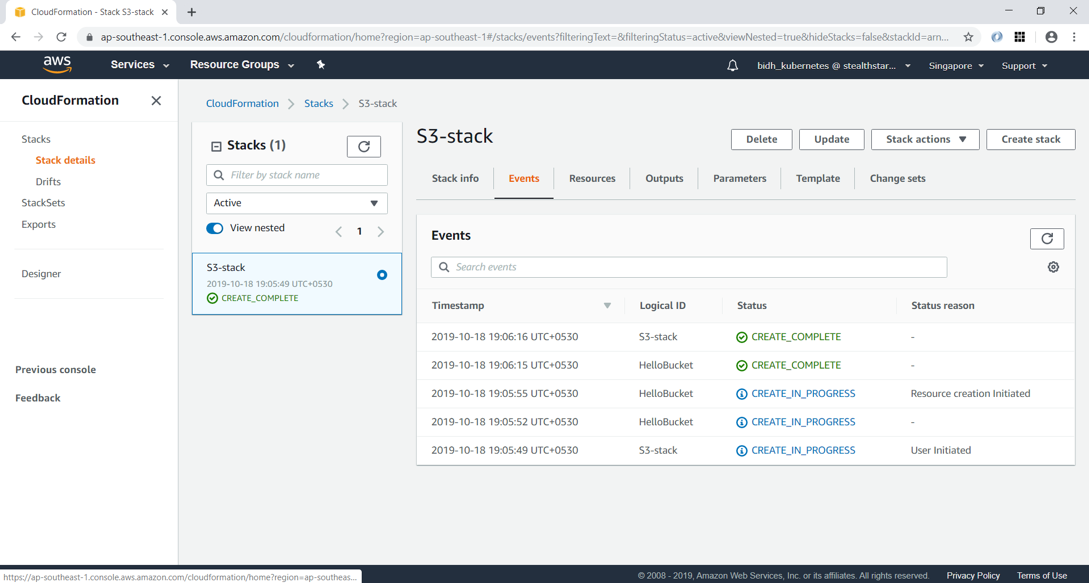
Click Next and then “Create stack”. After a few minutes, you can see that the stack creation is completed.
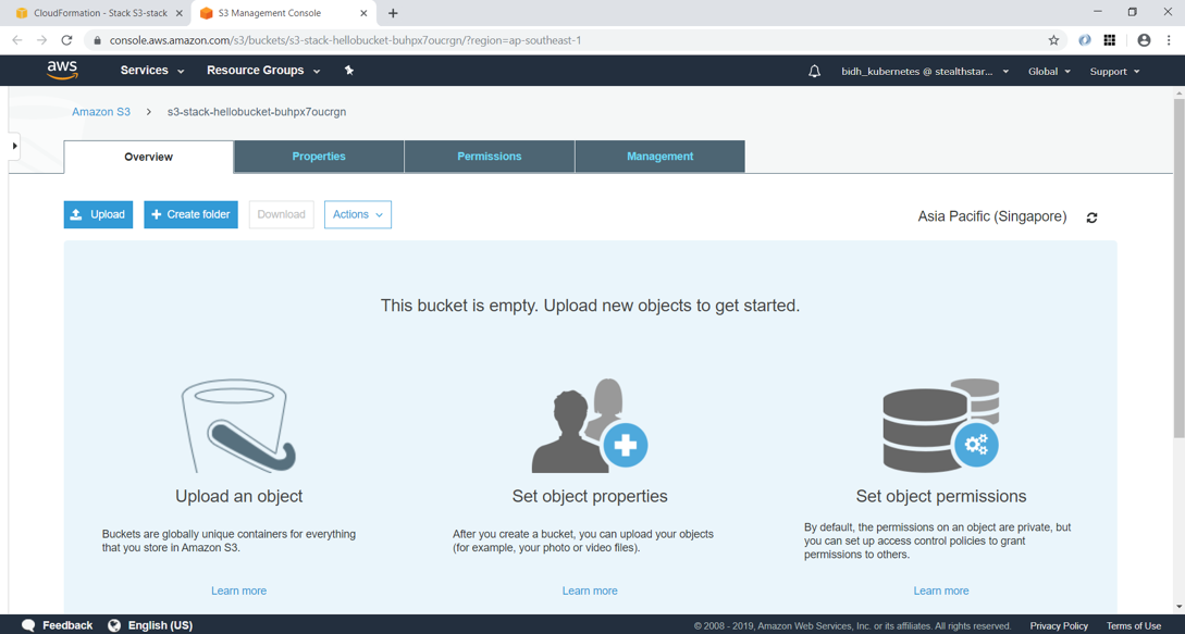
Clicking on the Resource tab, you can see that the S3 bucket has been created with name “s3-stack-hellobucket-buhpx7oucrgn”. AWS has provided this same since we didn’t specify the BucketName property in YAML.
Note that deleting the stack will delete the S3 bucket which it had created.
4. Intrinsic functions
AWS CloudFormation provides several built-in functions that
help you manage your stacks.
In the below example, we create two resources – a Security Group and an EC2 Instance, which uses this Security Group. We can refer to the Security Group resource using the !Ref function.
Fn::GetAtt – returns the value of an attribute
from a resource in the template.
Fn::Join – appends a set of values into a single
value, separated by the specified delimiter. If a delimiter is an empty string,
the set of values are concatenated with no delimiter.
Fn::Sub – substitutes variables in an input
string with values that you specify. In our templates, we can use this function
to construct commands or outputs that include values that aren’t available
until we create or update a stack.
5. Parameters
Parameters enable us to input custom values to your template each time you create or update a stack.
Pseudo parameters are parameters that are predefined by AWS CloudFormation. We do not declare them in our template. Use them the same way as we would a parameter as the argument for the Ref function.
Commonly used pseudo parameters:
AWS:
Region – Returns a string representing the AWS Region in which the
encompassing resource is being created, such as us-west-2
AWS::StackName – Returns the name of the stack as specified during cloudformation
create-stack, such as teststack
7. Mappings
The optional Mappings section matches a key to a corresponding set of named values. For example, if you want to set values based on a region, we can create a mapping that uses the region name as a key and contains the values we want to specify for each specific region. We use the Fn::FindInMap intrinsic function to retrieve values in a map.
We cannot include parameters, pseudo parameters, or intrinsic functions in the Mappings section.
The optional Outputs section declares output values that we
can import into other stacks (to create cross-stack references), return in
response (to describe stack calls), or view on the AWS CloudFormation console.
For example, we can output the S3 bucket name for a stack to make the bucket
easier to find.
In the below example, the output named StackVPC returns the ID of a VPC, and then exports the value for cross-stack referencing with the name VPCID appended to the stack’s name.
Outputs:
  StackVPC:
    Description: The ID of the VPC
    Value: !Ref MyVPC
    Export:
      Name: !Sub "${AWS::StackName}-VPCID"
There is little doubt that data will guide the next generation of business strategy and will bring new efficiencies across industries. But for that to happen, organizations must be able to extract insights from their data.
Qubole is an ideal platform to activate end-to-end data processing in organizations. It combines all types of data – structured, unstructured, and legacy offline data – into a single data pipeline and turns it into rich insights by adding AI, ML, and deep analytics tools to the mix.
It scales seamlessly to accommodate more users and new data without adding administrative overheads and lowers cloud costs significantly. Simply put, Qubole is a platform that puts big data on the cloud to power business decisions based on real-time analytics.
At CloudIQ Technologies, our data experts have deployed Qubole’s cloud-native data systems for many of our clients, and the results have been outstanding. Here is an article from one of our data engineers that provides an overview of how to setup Qubole to use AWS environment and create and run spark clusters.
AWS Access Configuration:
In order for Qubole to create and run a cluster, we have to grant Qubole access to our AWS environment. We can grant access based on a key or a role. We will use role-based authentication.
Step 1: Login to Qubole
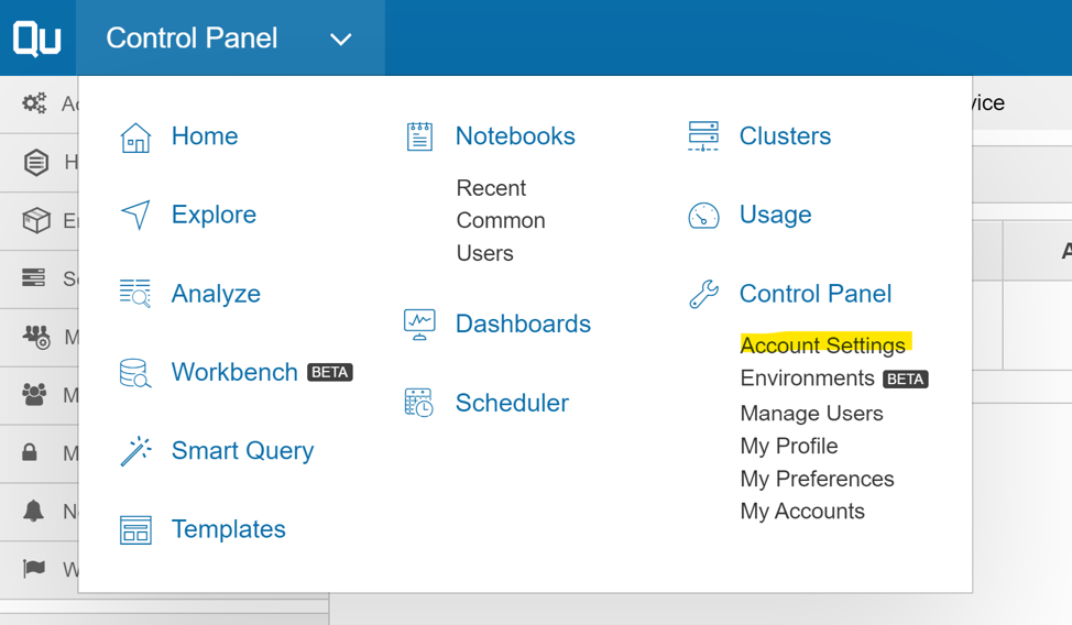
Step 2: Click on the menu at the top left corner and select “Account Settings” under the Control Panel.
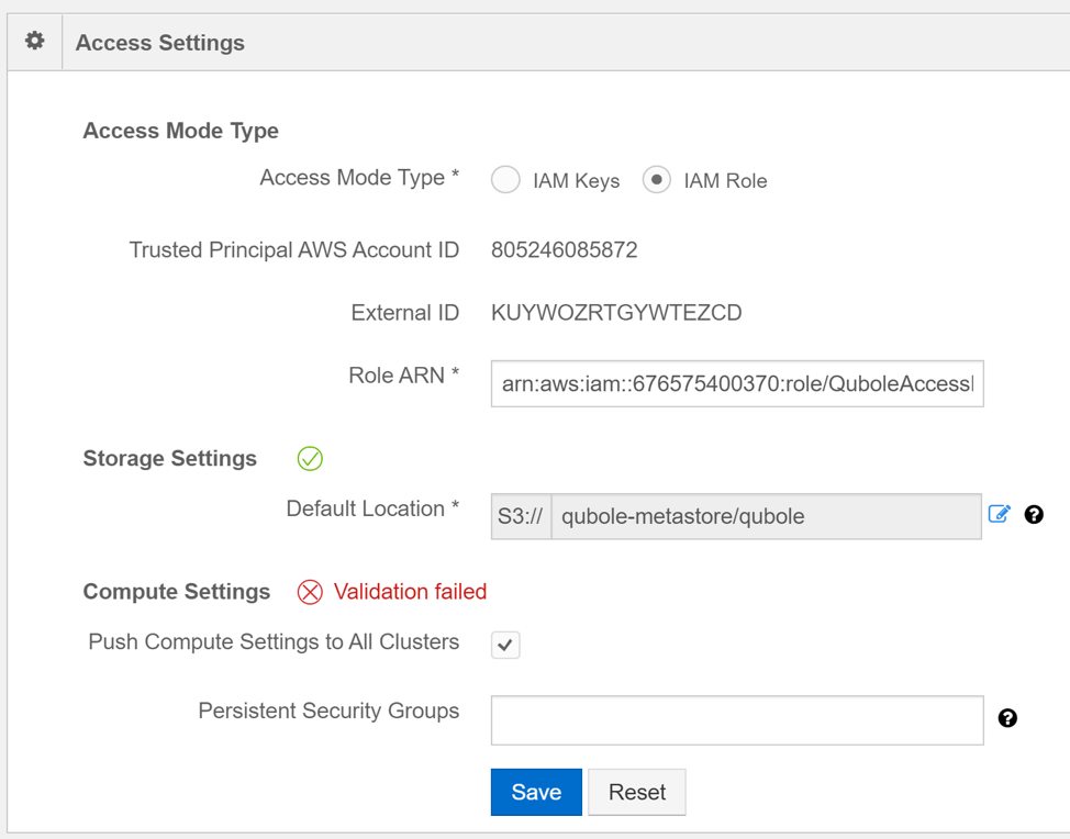
Step 3: Scroll down to Access settings
Step 4: Switch Access mode to “IAM Role”
Step 5: Copy the Trusted Principal AWS Account ID and External ID
Step 6: Use the copied values to create a QuboleAccessRole in the AWS account (using the cloudformation template)
Step 7: Copy the Role ARN of the QuboleAccessRole and enter it in the Role ARN field
Step 8: Enter the S3 bucket location where the Qubole metadata will be stored in the “Default Location” field.
Step 9: Click Save
Spark Cluster
Create a cluster
The below steps will help create a new Spark cluster in Qubole.
Step 1: Click on the top-left dropdown menu and select “Cluster”
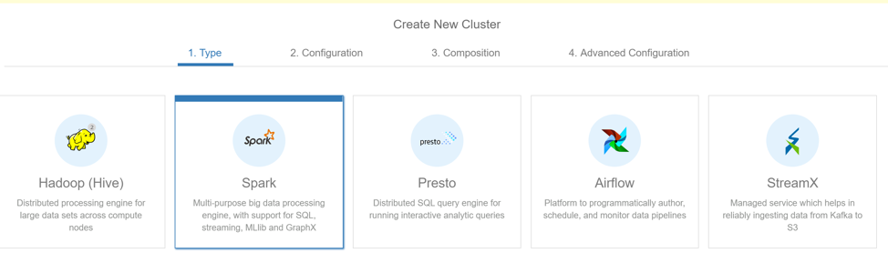
Step 2: Click on “+New” button
Step 3: Select “Spark” and click “Next”
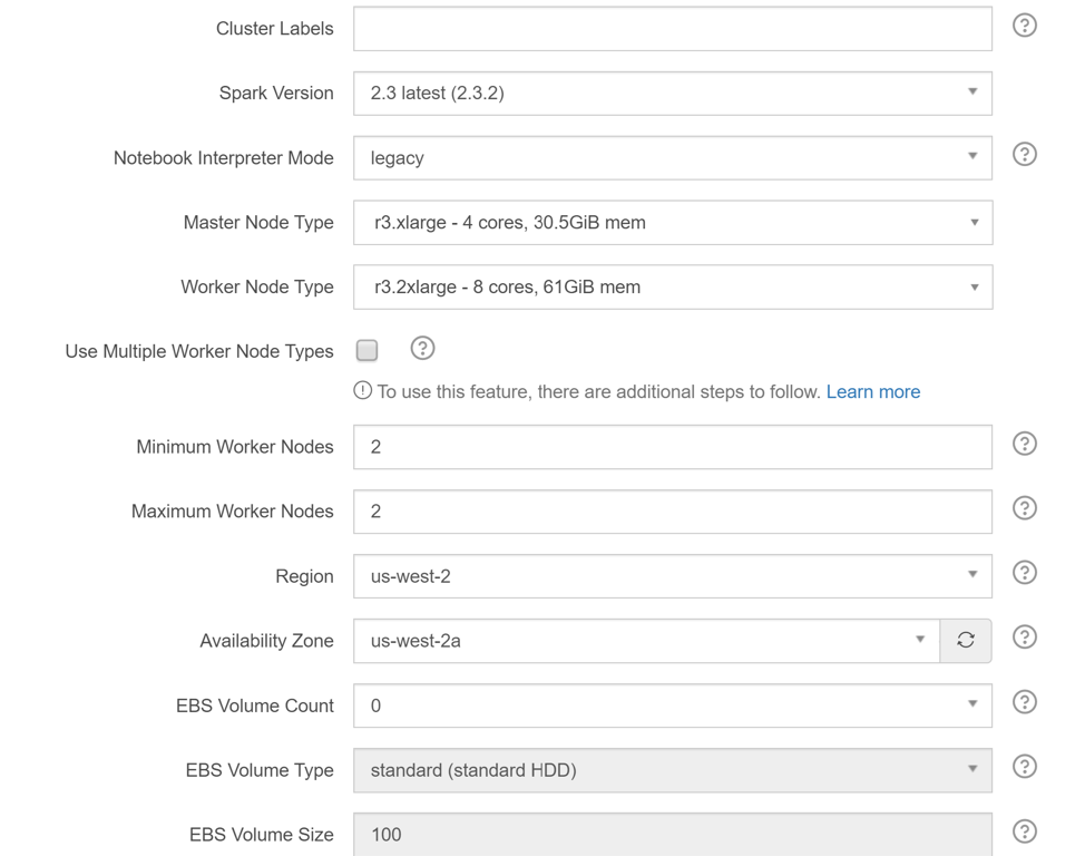
Step 4: Provide a name for the cluster in the “Cluster Labels” field
Step 5: Select the version of Spark to run, Master Node Type, Worker Node Type, Minimum and Maximum nodes
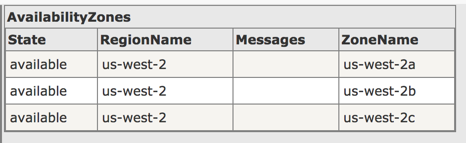
Step 6: Select Region as us-west-2
Step 7: Select Availability Zone as us-west-2a
Step 8: Click “Next”
Step 9: In the Composition screen, you can select the type of nodes that will be spun up.
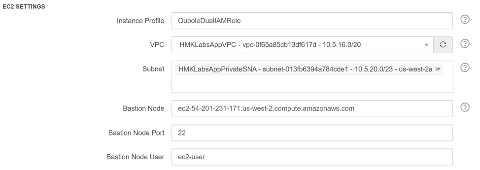
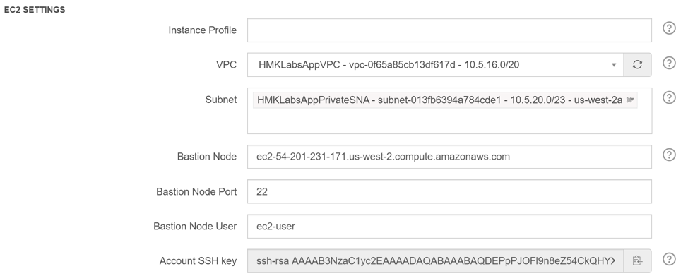
Step 10: In the Advanced Configuration screen, proceed to EC2 settings
Step 11: Enter “QuboleDualIAMRole” in the “Instance Profile” field
Step 12: Select “AppVPC” in VPC field
Step 13: Select “AppPrivateSNA” under Subnet field
Step 14: Enter the ip address of the Bastion node in the “Bastion Node” field
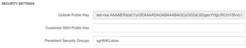
Step 15: Scroll to the bottom and enter “AppQuboleClusterSG” (security group for the cluster) in the “Persistent Security Group” field
Step 16: Click on “Create”
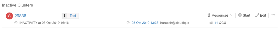
Run a cluster
To start a cluster, click on the dropdown menu on the top left corner and select cluster. Now click on “Start” button next to the cluster that needs to be started. A cluster is also automatically started when a job is submitted for the cluster.
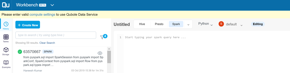
Submit a job
One of the simplest ways to run a spark job is to submit it through the workbench. You can navigate to the workbench from the drop-down menu at the top left corner. In the workbench, click on “+Create New”. Then select “Spark” next to the title of the job. Once you select Spark, an optional drop-down appears where you can choose “Python”. In the last drop-down menu, select the spark cluster where you want to execute the job. If this cluster is not active, it will be activated automatically. Enter your spark job in the window below. When complete, click on “Run” to run the job.
Airflow Cluster
Airflow scheduler can be used to run various jobs in a sequence. Let’s take a look at configuring an Airflow cluster in Qubole.
Setting up DataStore
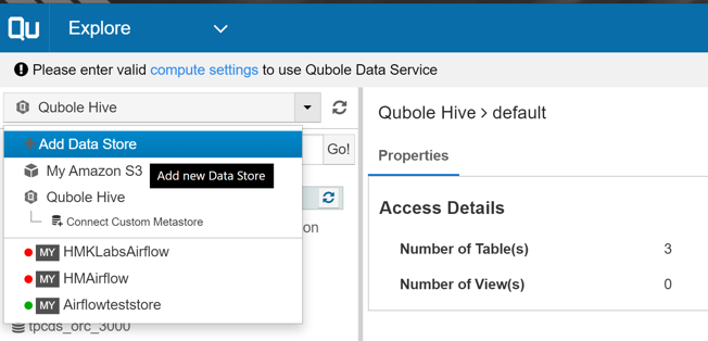
The first step in creating an airflow cluster is to set up a datastore. Make sure that the MySQL db is up and running and contains a database for airflow. Now, select “Explore” from the dropdown menu at the top left corner. On the left hand menu, drop down the selection menu showing “Qubole Hive” and select “+Add Data Store”
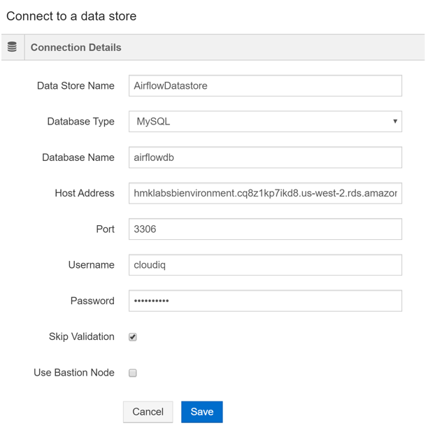
In the new screen, provide a name for the data store. Select “MySQL” as the database type. Enter the database name for the airflow database (The database should already be created in MySQL). Enter the host address as “hmklabsbienvironment.cq8z1kp7ikd8.us-west-2.rds.amazonaws.com”. Enter the username and password. Make sure to select “Skip Validation”. Since the MySQL db is in a private VPC, Qubole does not have access to it and will not be able to validate.
Configuring Airflow Cluster
Step 1: Click on the top left drop-down
menu and select “Cluster”
Step 2: Click on “+New” button
Step 3: Select “Airflow” in the type of
cluster and click “Next”
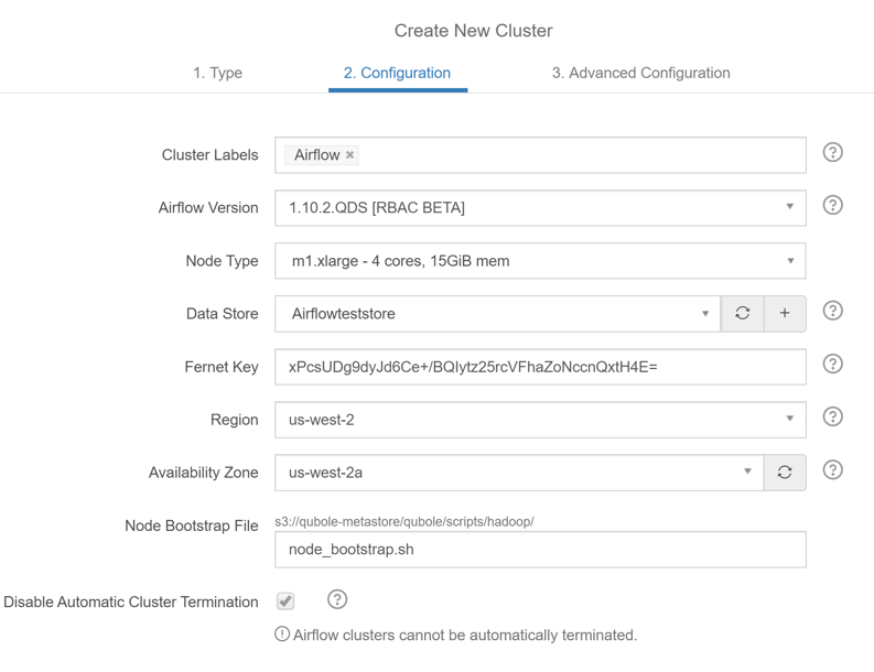
Step 4: Give a cluster name. Select the
airflow version, node type.
Step 5: Select the datastore which points
to the MySQL
Step 6: Select the us-west-2 as the Region
Step 7: Select us-west-2a as the Availability zone
Step 8: Click next to go to Advanced
Configuration
Step 9: Select AppVPC as the VPC
Step 10: Select AppPrivateSNA as the Subnet
Step 11: Enter the Bastion Node information
Step 12: Scroll to the bottom and enter AppQuboleClusterSG
as the Persistent Security Groups
Step 13: Click on create
Once the cluster is
created, you can run it by clicking on “Start” next to the cluster’s
name.
Containers are being embraced at a breakneck speed – developers love them, and they are great for business because they deliver speed and scale in a cost-efficient manner. So much so, that container technology seems to be overtaking VMs – especially with container orchestration tools like Kubernetes, making them simpler to manage and extracting higher efficiency and speed from them.
Kubernetes cluster architecture
Kubernetes provides an open-source platform for simplifying multi-cloud environments. The disparities between different cloud providers are a roadblock for developers and Kubernetes helps by streamlining and standardizing container-based applications.
Kubernetes clusters are the architectural foundation that drives this simplicity and makes it possible for users to get the functionality they need at scale and with ease. Here are some of the functionalities of Kubernetes –
Kubernetes distributes workload efficiently across all open
resources and reduces traffic spikes or outages.
It simplifies application deployment regardless of the size of
the cluster
It automates horizontal scaling
It monitors against app failure with constant node and container
health checks and performs self-healing and replication to resolve any failure
issues.
All this makes the work of developers faster and frees up their time and attention from trivial repetitive tasks allowing them to build applications better and faster! For the organization, the benefits are three-fold – higher productivity, better products and, finally, cost efficiencies.
Let’s move to the specifics now and find out how to set up a Kubernetes Cluster on the RHEL 7.6 operating system on AWS.
Prerequisites:
You should have a VPC
available.
A subnet within that VPC, into
which you will place your cluster.
You should have Security Groups
for the Control Plane Load Balancer and the Nodes created.
You should have created the
Control Plane Load Balancer.
A bastion host, or jump box,
with a public IP within your VPC from which you can secure shell into your VMs.
A pem file for your AWS region,
which you will use to secure shell into your VMs.
Creating the IAM Roles
You will need to create 2 IAM roles: one for the Master(s), and one for the worker nodes.
Master Role
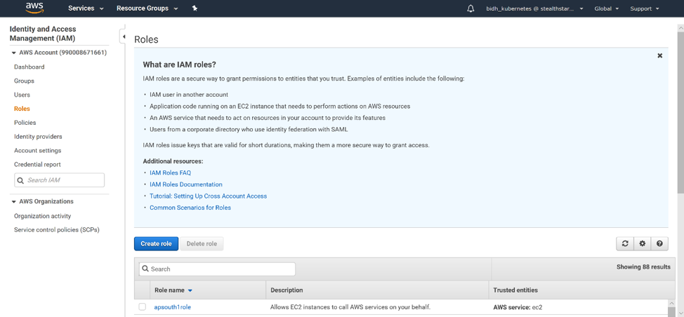
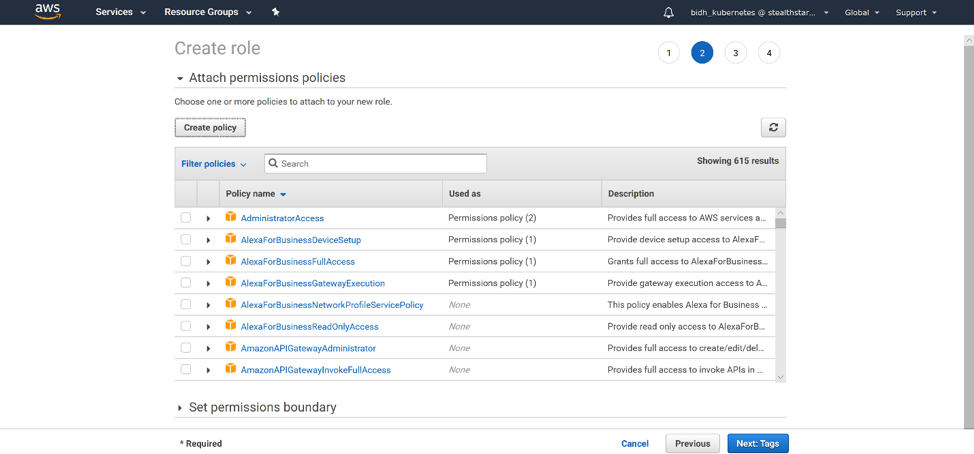
To create an IAM role, go to the IAM (Identity and Access Management) page in the AWS console. On the left-hand menu, click ‘Roles’. Then click ‘Create Role’.
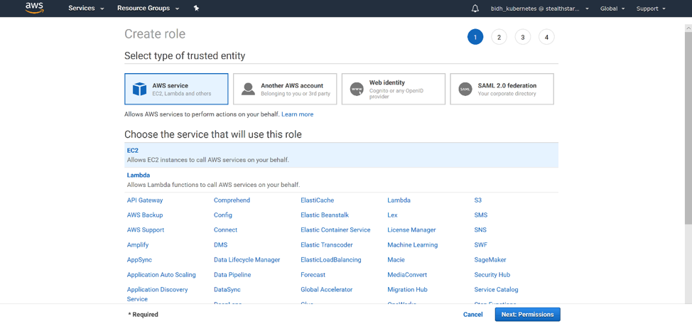
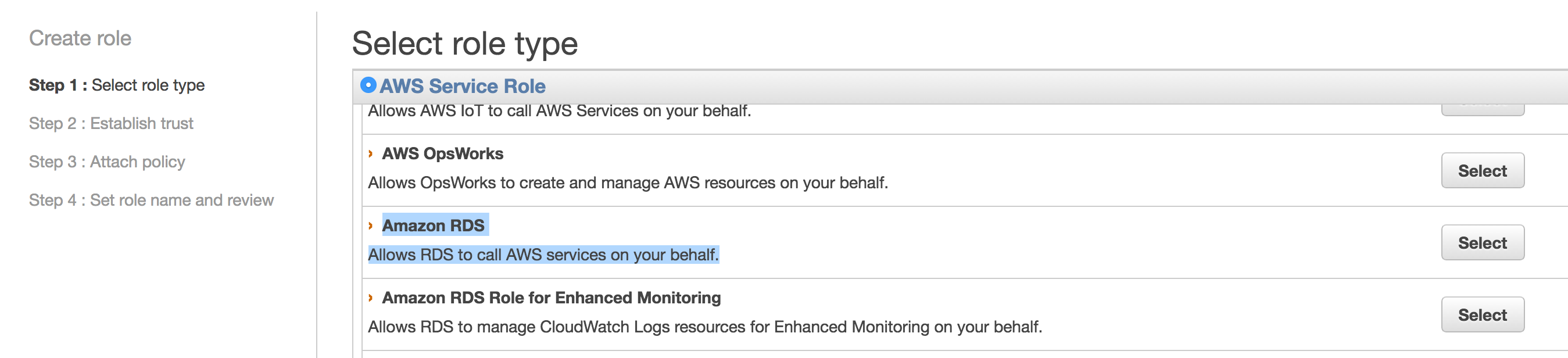
Select the service that will use this role. By default, it is EC2, which is what we want. Then click “Next: Permissions”.
Click ‘Create Policy’. The Create Policy page opens in a new tab.
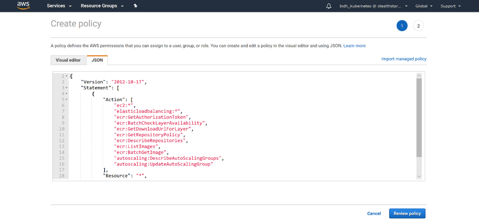
Click on the ‘JSONtab’. Then paste this json into it:
This json defines the permissions that your master nodes will need.
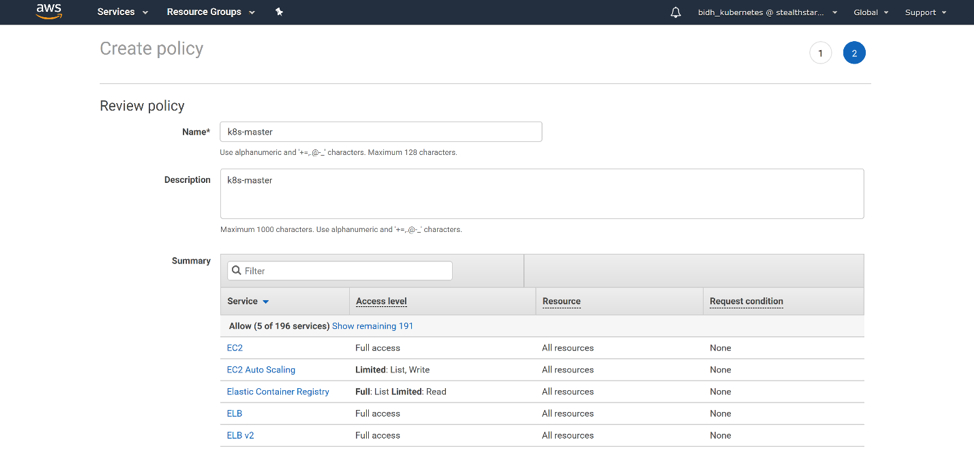
Click ‘Review Policy’. Then give your policy a name and a description.
Click ‘Create
Policy’ and your policy is created!
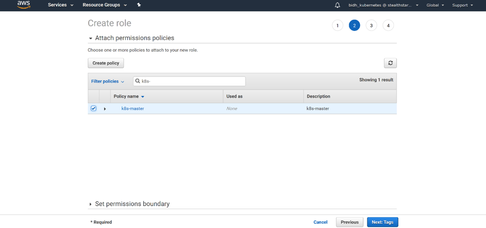
Back on the Create Role page, refresh your policy list, and filter for the policy you just created. Select it and click ‘Next: Tags’.
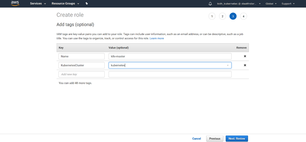
You should add 2 tags: Name, with a name for your role, and KubernetesCluster, with the name of the cluster that you are going to create. Click ‘Next: Review’.
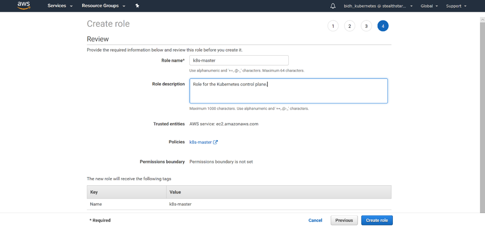
Give your role a name and a description. Click ‘Create Role’ and your role is created!
Node Role
For the node role, you will follow similar steps, except that you will use the following json:
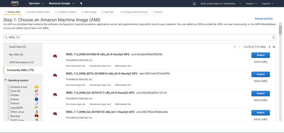
We will use RHEL 7.6 for our cluster because RHEL 8.0 uses iptables v1.8, and kube-proxy does not work well with iptables v1.8. However, kube-proxy works with iptables v1.4, which is installed on RHEL 7.6. We will use the x86_64 architecture.
Log into the AWS console. Go to the EC2 home page and click ‘Launch Instance’. We will search under Community AMIs for our image.
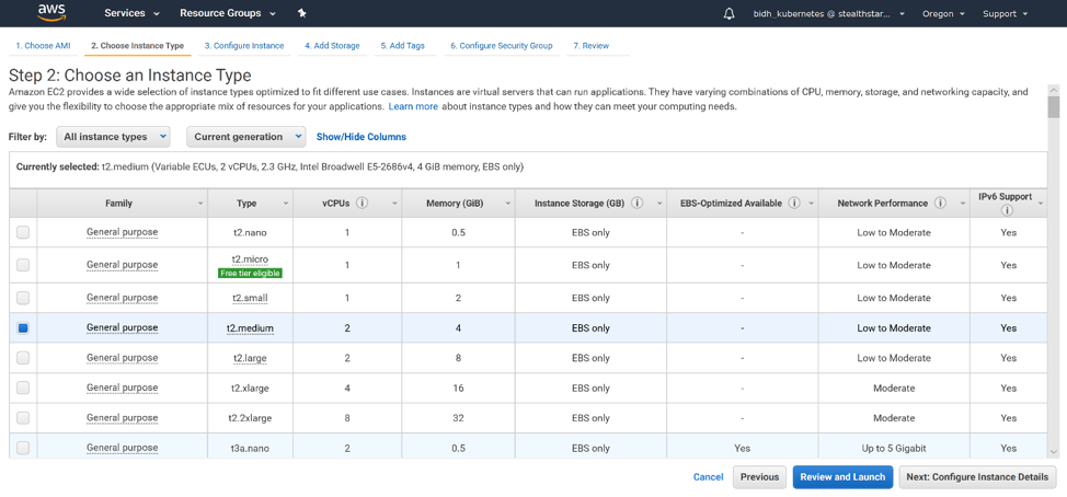
Click ‘Select’. Then choose your instance type. T2.medium should suffice for a Kubernetes master. Click ‘Next: Configure Instance Details’.
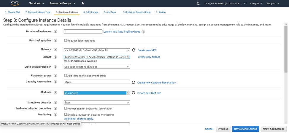
We will use only 1 instance. For an HA cluster, you will want more. Select your network and your subnet. For the purposes of this tutorial, we will enable auto-assigning a public IP. In production, you would probably not want your master to have a public IP. But you would need to make sure that your subnet is configured correctly with the appropriate NAT and route tables. Select the IAM role you created. Then click ‘Next: Add Storage’.
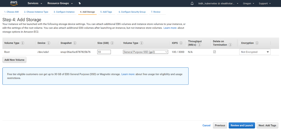
The default, 10 GB of storage, should be adequate for a Kubernetes master. Click ‘Next: Add Tags’.
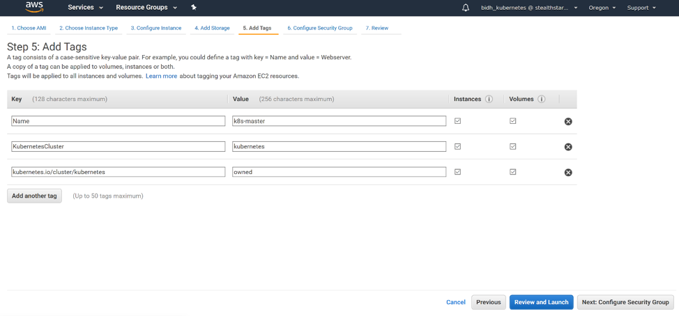
We will add 3 tags: Name, with the name of your master; KubernetesCluster, with the name of your cluster; and kubernetes.io/cluster/<name of your cluster>, with the value owned. Click ‘Next: Configure Security Group’.
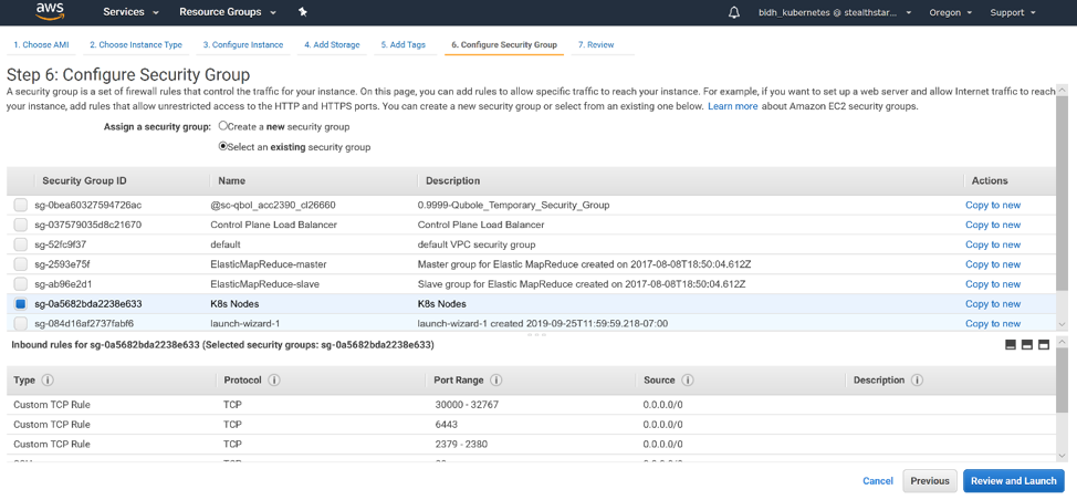
Select “Select an existing security group” and select the security group you created for your Kubernetes nodes. Click ‘Review and Launch’.
Click ‘Launch’. Select “Choose an Existing Key Pair”. Select the key pair from the drop-down. Check the “I acknowledge” box. You should have the private key file saved on the machine from which you plan to secure shell into your master; otherwise you will not be able to ssh into the master! Click ‘Launch Instances’ and your master is created.
Provisioning the Auto Scaling Group
Your worker nodes should be behind an Auto Scaling group. Under Auto Scaling in the left-hand menu of the AWS console, click ‘Auto Scaling Groups’. Click ‘Create Auto Scaling Group’. On the next page, click ‘Get Started’.
Under
“Choose AMI”, select RHEL 7.6 x86_64 under Community AMIs, as you did for the
master.
When choosing your instance type, be
mindful of what applications you want to run on your Kubernetes cluster and
their resource needs. Be sure to provision a size with sufficient CPUs and
memory.
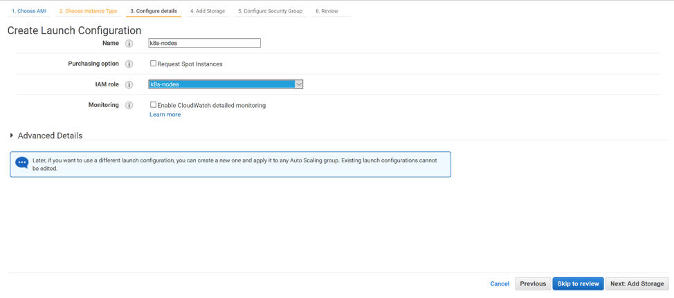
Under “Configure Details”, give your autoscaling group a name and select the IAM role you configured for your Kubernetes nodes.
When
selecting your storage size, be mindful of the storage requirements of your applications
that you want to run on Kubernetes. A database application, for example, would
need plenty of storage.
Select
the security group that you configured for Kubernetes nodes.
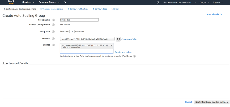
Click ‘Create Launch Configuration’. Then select your key pair as you did for the master. Click ‘Create Launch Configuration’ and you are taken to the ‘Configure Auto Scaling Group Details’ page. Give your group a name. Select a group size. For our purpose, 2 nodes will suffice. Select the same subnet on which you placed your master. Click ‘Next: Configure Scaling policies’.
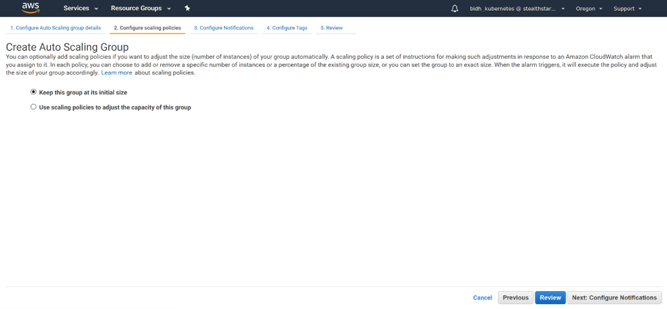
For this tutorial, we will select “Keep this group at its initial size”. For a production cluster with variability in usage, you may want to use scaling policies to adjust the capacity of the group. Click ‘Next: Configure Notifications’.
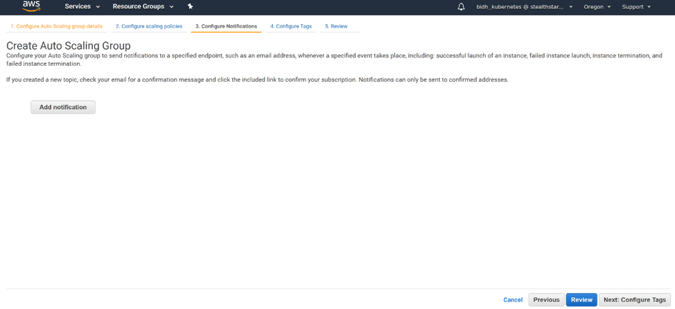
We will not add any notifications in this tutorial. Click ‘Next: Configure Tags’.
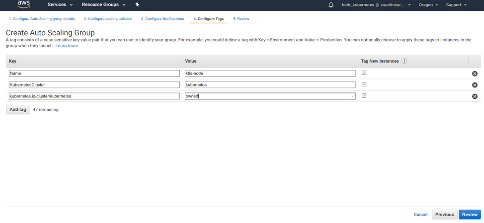
We will add 3 tags: Name, with the name of your nodes; KubernetesCluster, with the name of your cluster; and kubernetes.io/cluster/<your cluster name>, with the value owned. Click ‘Review’.
Click Create Auto Scaling Group and your
auto-scaling group is created!
Installing Kubernetes
Specific steps need to be followed to install Kubernetes. Run the following steps as sudo on your master(s) and worker nodes.
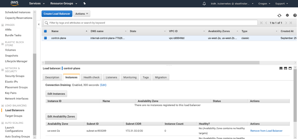
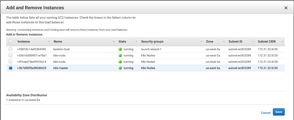
First, add your master(s) to the control plane load balancer as follows. Log into the AWS console, EC2 service, and on the left-hand menu, under Load Balancing, click ‘Load Balancers’. Select your load balancer and click the Instances tab in the bottom window. Click ‘Edit Instances’.
Select your master(s) and click ‘Save’.
We will create the Kubernetes cluster via a config file. You will need a token, the master’s private DNS name taken from the AWS console, the Load Balancer’s IP, and the Load Balancer’s DNS name. You can generate a Kubernetes token by running the following command on a machine on which you have installed kubeadm:
kubeadm token generate
To get the load balancer’s IP, you must execute a dig command. You install dig by running the following command as sudo:
I had a timeout error on the first attempt, but the command ran successfully the second time. Make a note of the output because you will need it to configure the nodes.
Finally, you have to label your master with the provider ID. That way, any load balancers you create for this node will automatically add the node as an AWS instance:
You can join worker nodes to the cluster by running the following command as sudo, which should have been printed out after running kubeadm init on the master:
In this article we will discuss how to create security groups in AWS for Kubernetes. The goal is to set up a Kubernetes cluster on AWS EC2, having provisioned your virtual machines. You are going to need two security groups: one for the control plane load balancer, and another for the VMs.
Creating a Security Group through the AWS Console
Prerequisite: You should have a VPC
(virtual private cloud) set up.
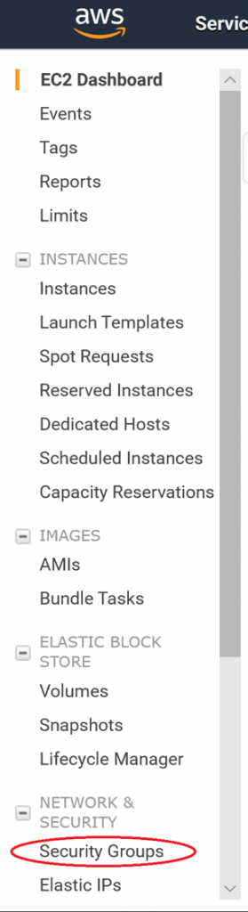
Log into the AWS EC2 (or VPC) console. On
the left-hand menu, under Network and Security, click Security Groups.
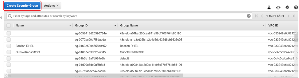
Click on Create Security Group.
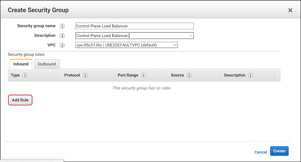
Enter a Name and a Description for your
Security Group. Then select your VPC from the drop-down menu. Click Add Rule.
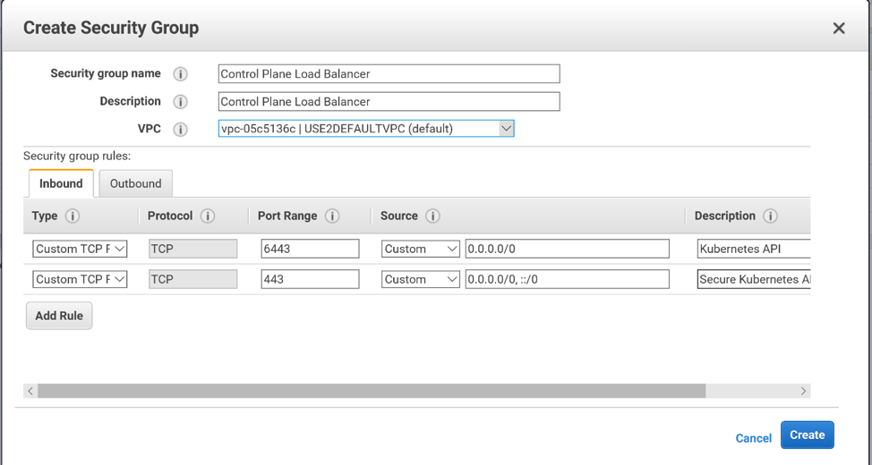
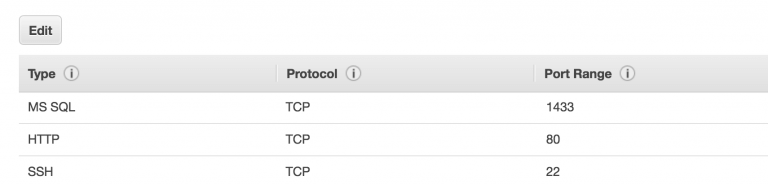
You will need 2 TCP ingress rules, one over
port 6443, another over port 443. We are choosing to allow the Source from
anywhere. In production you may want to restrict the CIDR, IP, or security
group that can reach this load balancer.
We are choosing to leave the outbound rules
as default, in which all outbound traffic is permitted.
Click Create and your security group is
created!
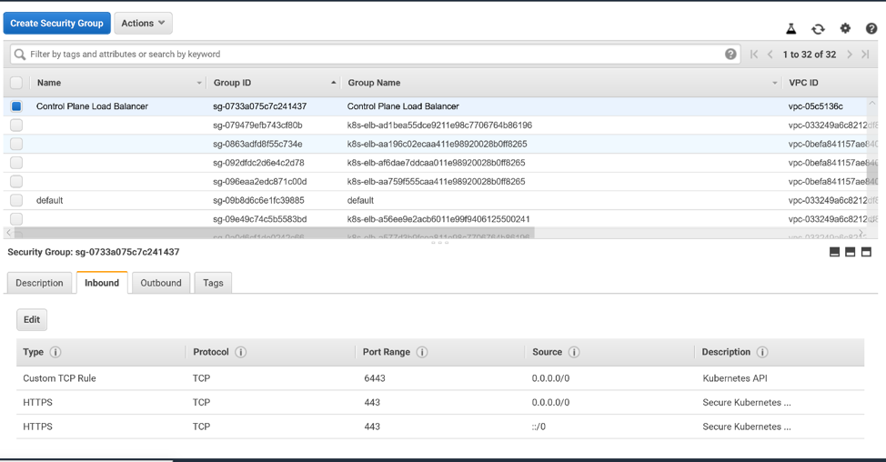
Select your security group in the console.
You may want to give your security group a Name (in addition to the Group Name
that you specified when creating it).
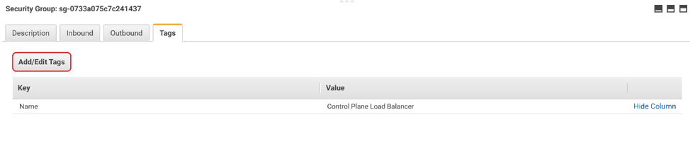
But you are not done yet: you must add tags
to your security group. These tags will alert AWS that this security group is
to be used for Kubernetes. Click
on the Tags tab at the bottom of the window. Then click Add/Edit Tags.
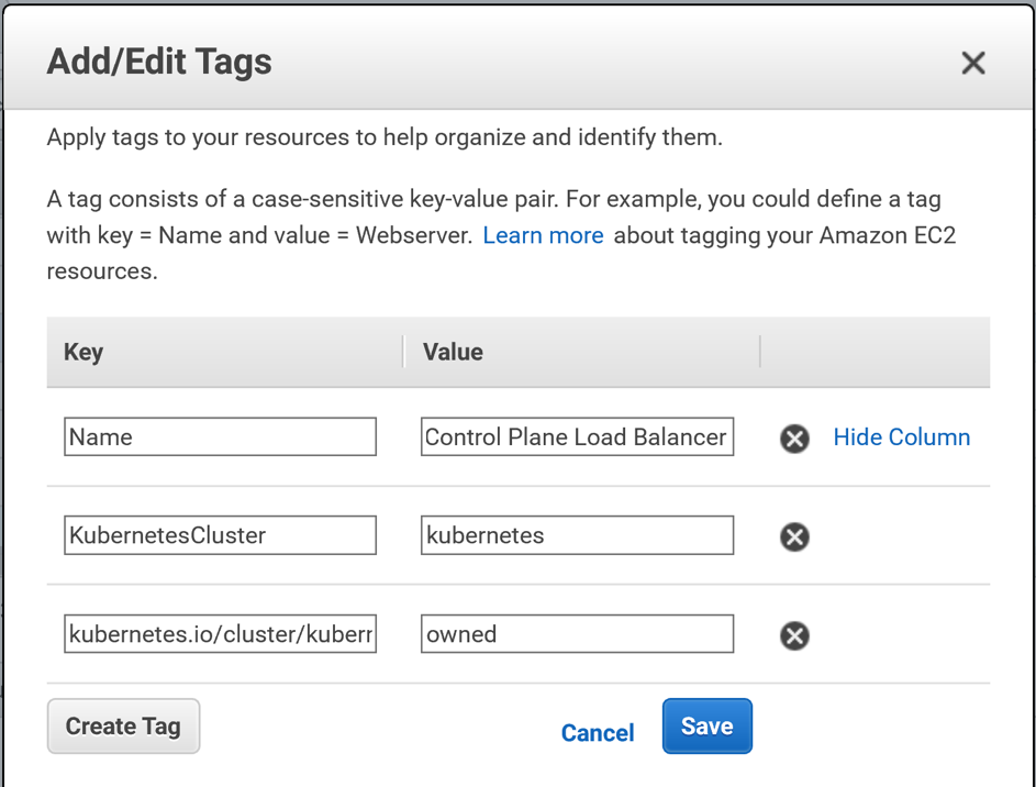
You will need 2 tags:
Name: KubernetesCluster. Value: <the name of your Kubernetes cluster>
Name: kubernetes.io/cluster/<the name of your Kubernetes cluster>. Value: owned
Click Save and your tags are saved!
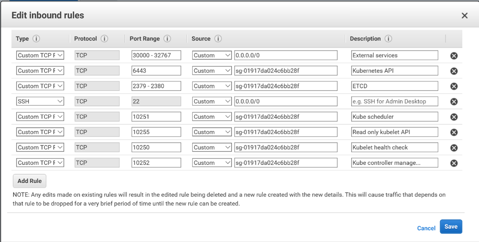
Creating a Security Group for the Virtual Machines
Follow the steps above to create a security group for your virtual
machines. Here are the ports that you will need to open for your control plane
VMs:
The master node:
22 for SSH from your bastion host
6443 for the Kubernetes API Server
2379-2380 for the ETCD server
10250 for the Kubelet health check
10252 for the Kube controller manager
10255 for the read only kubelet API
The worker nodes:
22 for SSH
10250 for the kubelet health check
30000-32767 for external applications. However, it is more likely that you will expose external applications to outside the cluster via load balancers, and restrict access to these ports to within your vpc.
10255 for the read only kubelet API
We have chosen to combine the master and
the worker rules into one security group for convenience. You may want to
separate them into 2 security groups for extra security.
Follow the step-by-step instructions detailed above and you will have
successfully created AWS Security Groups for Kubernetes.
Analytics is the discovery, interpretation, and communication of meaningful patterns in data; and the process of applying those patterns towards effective decision making. In other words, analytics can be understood as the connective tissue between data and effective decision making, within an organization. Organizations may apply analytics to business data to describe, predict, and improve business performance. Big data analytics is the complex process of examining large and varied data sets — or big data — to uncover information including hidden patterns, unknown correlations, market trends and customer preferences that can help organizations make informed business decisions.
Glue, Athena and QuickSight are 3 services under the Analytics Group of services offered by AWS. Glue is used for ETL, Athena for interactive queries and Quicksight for Business Intelligence (BI).
Glue
AWS Glue is a fully managed extract, transform, and load (ETL) service that makes it easy for customers to prepare and load their data for analytics. We can create and run an ETL job with a few clicks in the AWS Management Console. We simply point AWS Glue to our data stored on AWS, and AWS Glue discovers our data and stores the associated metadata (e.g. table definition and schema) in the AWS Glue Data Catalog. Once cataloged, our data is immediately searchable, queryable, and available for ETL.
In this blog we will look at 2 components of Glue – Crawlers and Jobs
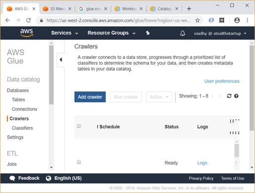
Glue Crawlers
Glue crawlers can scan data in all kinds of repositories, classify it, extract schema information from it, and store the metadata automatically in the AWS Glue Data Catalog. From there it can be used to guide ETL operations.
Suppose we have a file named people.json in S3 with the below contents:
Below are the steps to crawl this data and create a table in AWS Glue to store this data:
On the AWS Glue Console, click “Crawlers” and then “Add Crawler”
Give a name for your crawler and click next
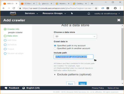
Select S3 as data source and under “Include path” give the location of json file on S3.
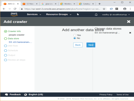
Since we are going to crawl data from only 1 dataset, select No in next screen and click Next
In next screen select an IAM role which has access to the S3 data store
Select Frequency as “Run on demand” in next screen.
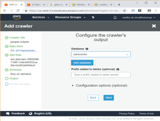
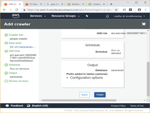
Select a Database to store the crawler’s output. I chose a database named “saravanan” in the screen below. If no database exists, Add a database using the link given
Review all details in next step and click Finish
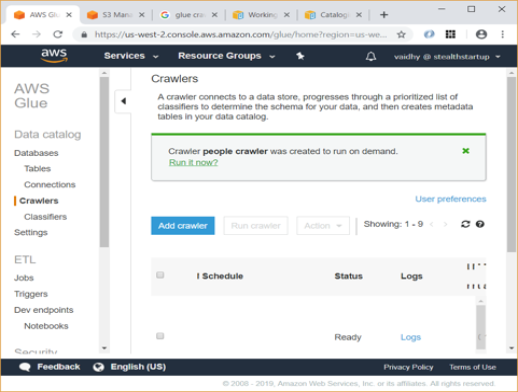
On next screen, click on “Run it now” to run the crawler
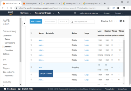
The crawler runs for around a minute and finally you will be able to see status as Stopping / Ready with Tables added count as 1.
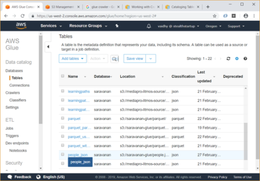
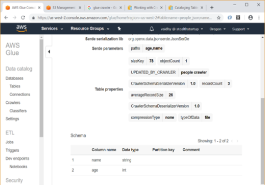
Now you can go to Tables link and see that a table named “people_json” has been created under “Saravanan” database.
Using the “View details” Action, and then scrolling down, you can see the schema for the table which Glue has automatically inferred and generated.
Glue jobs
The AWS Glue Jobs system provides managed infrastructure to orchestrate our ETL workflow. We can create jobs in AWS Glue that automate the scripts we use to extract, transform, and transfer data to different locations. Jobs can be scheduled and chained, or they can be triggered by events such as the arrival of new data.
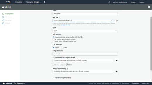
To add a new job using the console
Open the AWS Glue console, and choose the Jobs tab.
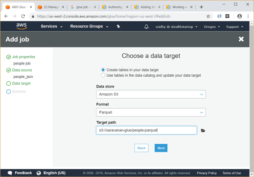
Choose Add job and follow the instructions in the Add job wizard. Below screens copy data from the table we created earlier to a parquet file named people-parquet in same S3 bucket. After the above job runs and completes, you will be able to verify in S3 that the output Parquet has been created.
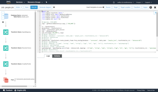
DynamicFrame
Glue Jobs use a data structure named DynamicFrame. A DynamicFrame is similar to a Spark DataFrame, except that each record is self-describing, so no schema is required initially. Instead, AWS Glue computes a schema on-the-fly when required, and explicitly encodes schema inconsistencies using a choice (or union) type.
Instead of just using the python job which Glue generates, we can code our own jobs using DynamicFrames and have
it run through Glue. The same Glue job on next page selects specific fields from 2 Glue tables, renames some of the fields, joins the tables and writes the joined table to S3 in parquet format.
Athena
Amazon Athena is an interactive query service that makes it easy to analyse data in Amazon S3 using standard SQL. Athena is serverless, so there is no infrastructure to manage, and we pay only for the queries that we run.
Athena is easy to use. We must simply point to our data in Amazon S3, define the schema, and start querying using standard SQL. Most results are delivered within seconds. With Athena, there’s no need for complex ETL jobs to prepare our data for analysis. This makes it easy for anyone with SQL skills to quickly analyse large-scale datasets.
Athena is out-of-the-box integrated with AWS Glue Data Catalog, allowing us to create a unified metadata repository across various services, crawl data sources to discover schemas and populate your Catalog with new and modified table and partition definitions, and maintain schema versioning.
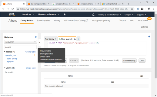
Since Athena uses same Data Catalog as Glue, we will be able to query and view properties of the people_json table which we created earlier using Glue.
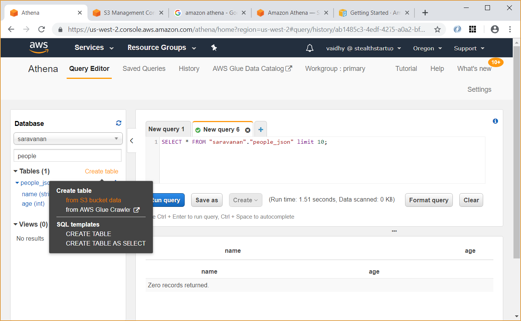
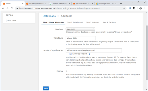
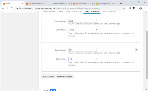
Also, we can create new table using data from S3 bucket data as shown below:
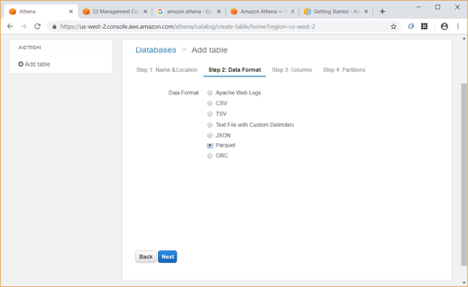
Unlike Glue, we have to explicitly give the data format (CSV, JSON, etc) and specify the column names and types while creating the table in Athena.
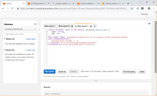
We can also manually create and query the tables using SQL as shown below:
QuickSight
Amazon QuickSight is a fast, cloud-powered business intelligence (BI) service that makes it easy for us to deliver insights to everyone in our organization.
QuickSight lets us create and publish interactive dashboards that can be accessed from browsers or mobile devices. We can embed dashboards into our applications, providing our customers with powerful self-service analytics.
QuickSight easily scales to tens of thousands of users without any software to install, servers to deploy, or infrastructure to manage.
Below are the steps to create a sample Analysis in QuickSight:
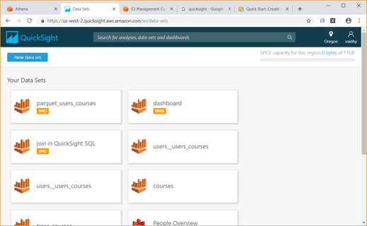
Any Analysis in QuickSight requires data from a Data Set. First click on the “Manage data” link at top right to list the Data Sets we currently have.
To create a new Data Set, click the “New data set” link
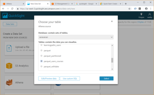
We can create Data Set from any of the Data sources listed here – uploading a file, S3, Athena table, etc.
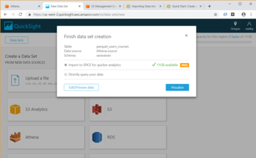
For our example, I am selecting Athena as data source and giving it a name “Athena source”. Then we must map this to a database / table in Athena.
After we select the Athena table, QuickSight provides us an option to import the data to SPICE. SPICE is Amazon QuickSight’s in-memory optimized calculation engine, designed specifically for fast, adhoc data visualization. SPICE stores our data in a system architected for high availability, where it is saved until we choose to delete it.
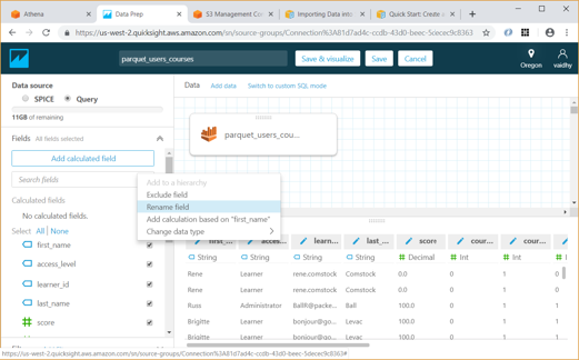
Using the Edit/Preview Data option above allows us to select the columns to be included in Data set and rename them if required.
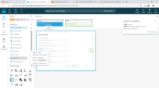
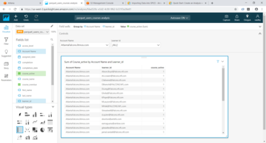
Once we click the “Save & visualize” link above, QuickSight starts creating an Analysis for us. For our exercise we will select the Table visual type from the list.
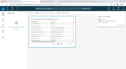
Add Account Name and User_id by dragging them from “Fields list” to “Group by” and course_active to “Value”
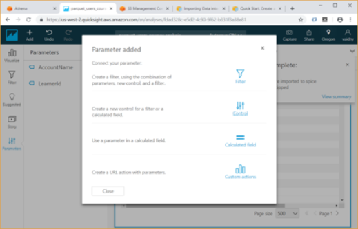
Now we will add 2 parameters for Account Name and Learner id by clicking on Parameters at bottom left. While creating the parameter use the option “Link to a data set field” for Values and link the parameter to the appropriate column in the Athena table
Once the parameters are added, create controls for the parameters. If we are adding 2 parameters with controls, we have option of showing only relevant values for second parameter based on the values selected for first parameter. For this select the “Show relevant values only” checkbox.
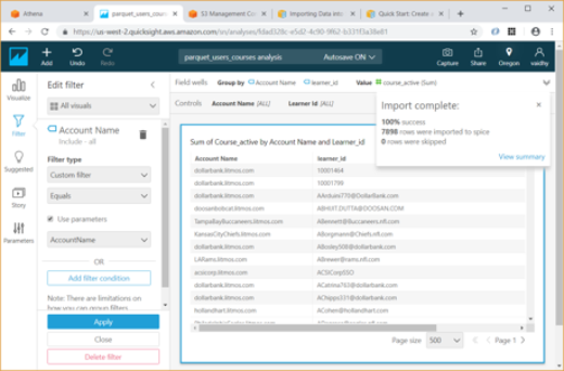
Next add 2 Custom filters for Account Name and Learner id. These filters should me mapped to the parameters we had created earlier. For this choose the Filter type as “Custom filter” and select the “Use parameters” checkbox.
Now using the Visualize option, we can verify if our Controls are working correctly
To share the Dashboard with others, use the share option on top towards the right and use publish dashboard. We can search for users of the AWS account by email and publish to selective users.
Amazon’s Alexa is the voice activated, interactive AI Bot, or intelligent personal assistant in the cloud that lets people speak with their Amazon Echo, Echo dot and other Amazon smart home devices. Alexa is designed to respond to number of commands and converse with people.
Alexa Skills are apps that give Alexa even more abilities. These skills can let her speak to more devices or websites.When the Alexa device is connected through wi-fi or Bluetooth to the internet, it wakes up by merely saying “ALEXA”. Alexa Skills radically expands the bots repertoire, allowing users to perform more actions with voice-activated control through Alexa.
Overview of Alexa Skill
The most important part of ALEXA skill is its interaction design. Alexa skills don’t have visual feedback like web or desk top applications and will guide the user through the skill using voice. All Alexa skill replies needs to tell the user clearly what the next options are.
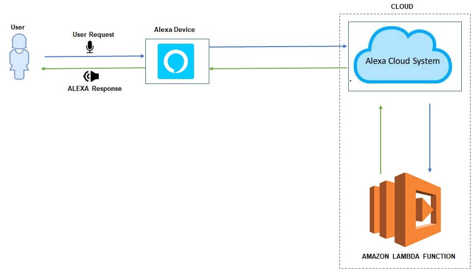
Functional Architechture
An Alexa skill is a small application that interacts with Alexa via an AWS Lambda function
Designing the Alexa Skill
The most important aspect of the skill is its Vocal interface. The skill should be interacting naturally with the user. The components of Alexa Skill are :
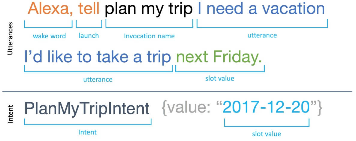
Alexa requires a word, often called as Wake phrase which would alert the device that they can expect a command immediately after.The Default wake phrase is ALEXA. It can also be Amazon, Echo,Computer.
Launch Phrase is the word that tells Alexa to trigger a skill. Examples of Launch phrase are “ OPEN”, “ASK” , “START”, “LAUNCH”.
Invocation name is the name of the skill.
Intents are the goals that the user is trying to achieve by invoking the skill.
Utterance tells alexa what the skill should do. Apart from Static utterances such as Start and Launch, dynamic commands can be added. These Dynamic commands are called slots.
Each intent can contain one or more slots. A Slot is the variable that is parsed and exposed to the application code.
Sampleutterances
Alexa has a built in natural language processing engine. To Map the verbal phrase to an intent, Alexa handles the complexity of natural language processing through the help of a manually curated file Sampleutterances.txt.
The first word in each line of SampleUtteranaces.txt is the intent name. The application code reads the value of the intent name and responds appropriately. Following the intent name, is the phrase that the user says to achieve that intent. The User might tell a phrase apart from those defined as Slots in the intent. The application is free to react differently based on the presence or value of the slot. To give Alexa the best chance of understanding users, it is recommended to include as many sample utterances as possible. Depending on the skill there could be n number of ever changing sample utterances.
The below example sums up the entire vocal interface
Build and Publish a new skill
Building and publishing a new skill in Alexa comprises of the below steps:
Interaction modelis a set of rules that defines the way the user interacts with your skill. As a part of an interaction model, Intents, Utterances are defined. The intent schema should be in JSON format and it should define an array of intents, each with a name, and an optional list of dynamic parts — slots. Alexa will automatically train itself with the provided interaction model.
3. Coding the Backend system:
Once the interaction model has been designed Code and deployment of the Lambda function has to be done.
For each intent, an input/output contract has to be implemented. The input is an IntentRequest which is a representation of the user’s request and includes all the slot values.
The response from alexa can be of multiple ways.
Ask the user a question and wait for response.
Give the details to the user and shut down.
Say nothing and shut down.
Alexa can either respond verbally or the response could be displayed on the phone.
4. Deploying the Backend system:
The skills can be deployed as an AWS Lambda function with code written in Java or Node.Js, Python or C#. The simplest approach would be the code in Node.Js.
5. Testing the Skill:
Testing of the Skill can either be done through the test simulator available in the Developer console account or through the device connected to the development account.
6. Publishing the Skill:
To Publish the skill, The skill has to be submitted by filling out the “Publishing Information” and the “Privacy & Compliance” sections
We typically get data feeds from our clients ( usually about ~ 5 – 20 GB) worth of data. We download these data files to our lab environment and use shell scripts to load the data into AURORA RDS . We wanted to avoid unnecessary data transfers and decided to setup data pipe line to automate the process and use S3 Buckets for file uploads from the clients.
In theory it’s very simple process of setting up data pipeline to load data from S3 Bucket into Aurora Instance .Even though it’s trivial , setting up this process is very convoluted multi step process . It’s not as simple as it sounds . Welcome to Managed services world.
STEPS INVOLVED :
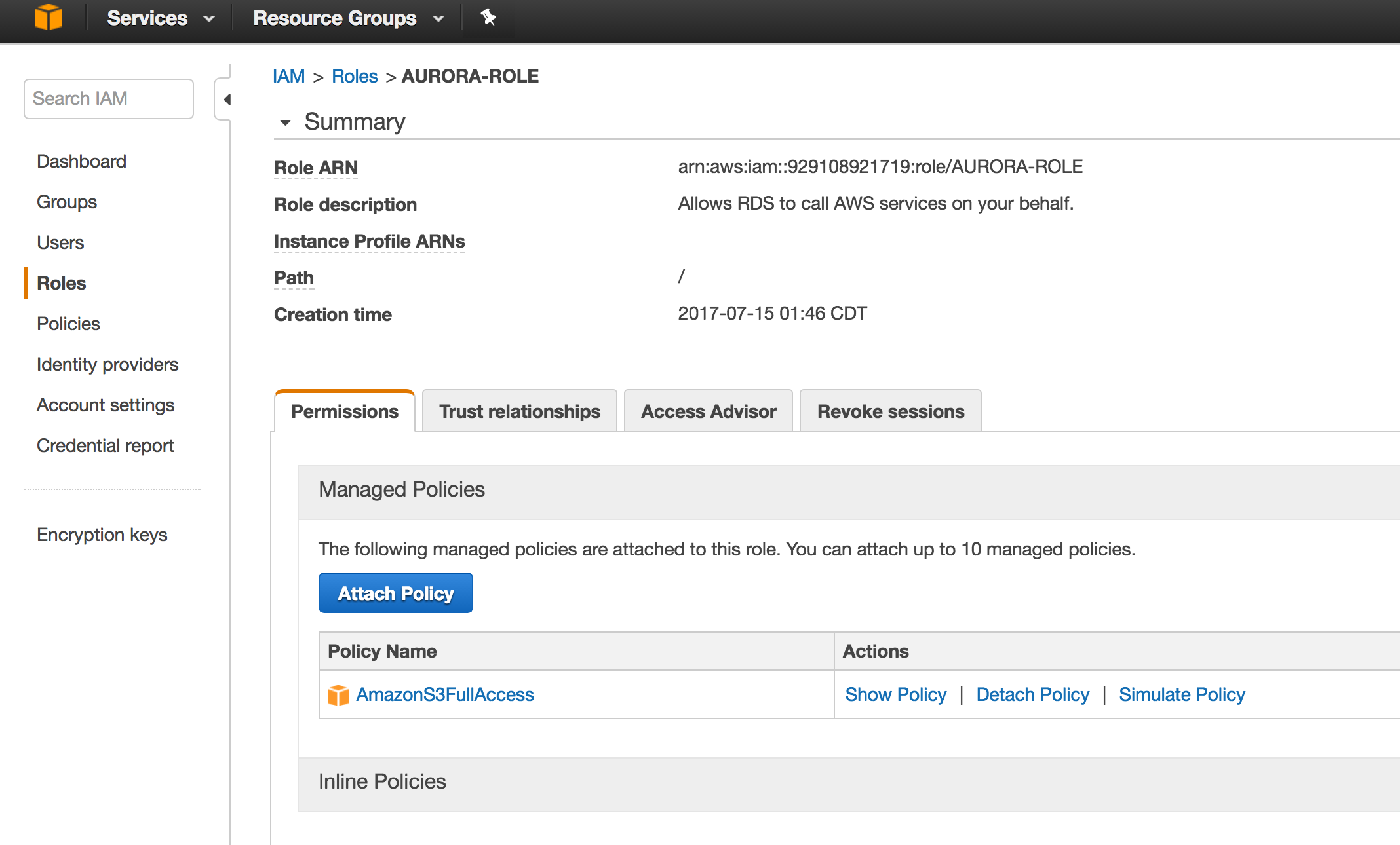
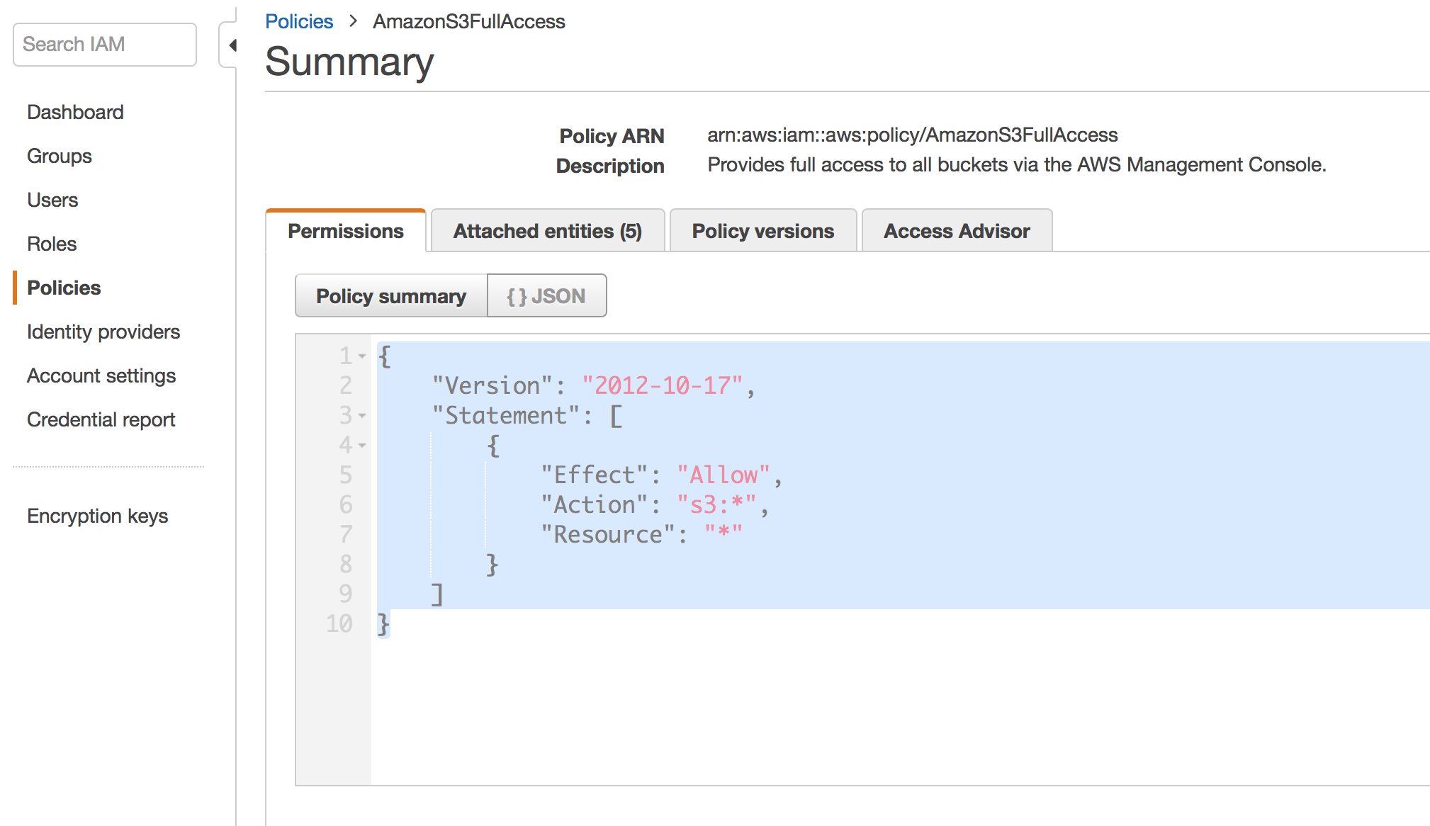
Create ROLE and Attach S3 Bucket Policy :
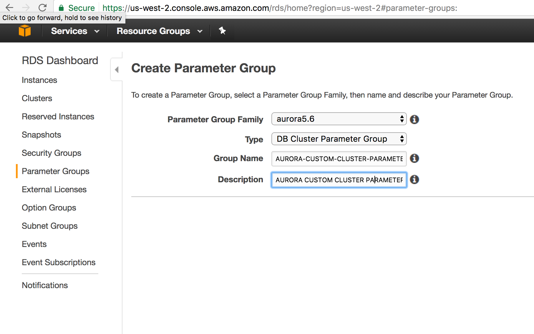
Create Cluster Parameter Group
Modify Custom Parameter Groups to use ROLE
REBOOT AURORA INSTANCE
GRANT AURORA INSTANCE ACCESS TO S3 BUCKET
By default aurora cannot access S3 Buckets and we all know it’s just common sense default setup to reduce the surface area for better security.
For EC2 Machines you can attach a role and the EC2 machines can access other AWS services on behalf of role assigned to the Instance.Same method is applicable for AURORA RDS. You Can associate a role to AURORA RDS which has required permissions to S3 Bucket .
There are ton of documentation on how to create a role and attach policies . It’s pretty widely adopted best practice in AWS world. Based on AWS Documentation, AWS Rotates access keys attached to these roles automatically. From security aspect , its lot better than using hard coded Access Keys.
In Traditional Datacenter world , you would typically run few configuration commands to change configuration options .( Think of sp_configure in SQL Server ).
In AWS RDS World , its tricky . By default configurations gets attached to your AURORA Cluster . If you need to override any default configuration , you have to create your own DB Cluster Parameter Group and modify your RDS instance to use the custom DB Cluster Parameter Group you created.Now you can edit your configuration values .
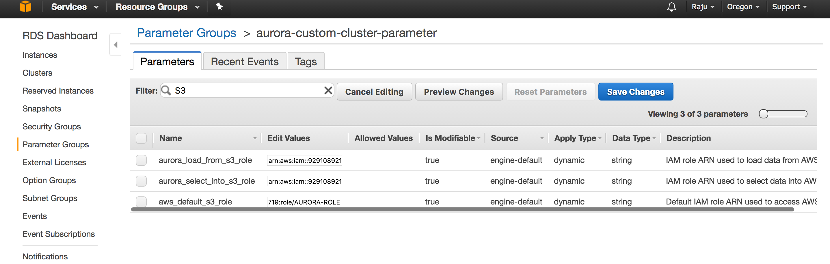
The way you attach a ROLE to AURORA RDS is through Cluster parameter group .
These three configuration options are related to interaction with S3 Buckets.
aws_default_s3_role
aurora_load_from_s3_role
aurora_select_into_s3_role
Get the ARN for your Role and modify above configuration values from default empty string to ROLE ARN value.
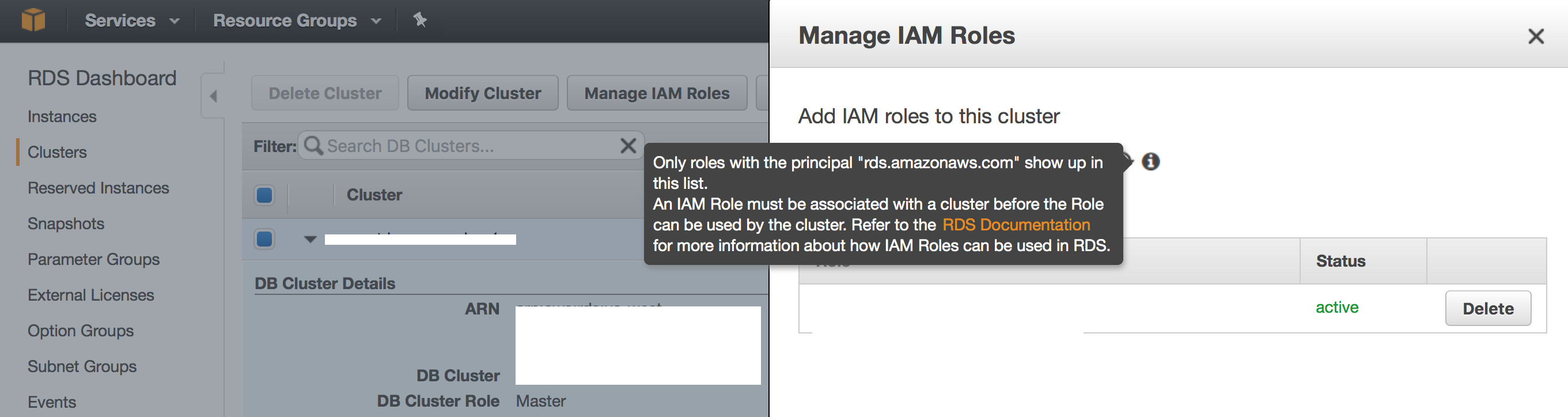
Then you need to modify your Aurora instance and select to use the role . It should show up in the drop down menu in the modify role tab.
GRANT AURORA LOGIN LOAD FILE PERMISSION
        GRANT LOAD FROM S3 ON *.* TO user@domain-or-ip-address
        GRANT LOAD FROM S3 ON *.* TO 'aurora-load-svc'@'%'
REBOOT AURORA INSTANCE
Without Reboot you will be spending lot of time troubleshooting. You need to reboot to the AURORA Instance for new cluster parameter values to take effect.
After this you will be be able to execute the LOAD FILE FROM S3 to AURORA .
Screen Shots :
Create ROLE and Attach Policy :
Attach S3 Bucket Policy :
Create Parameter Group :
Modify Custom Parameter Groups
Modify AURORA RDS Instance to use ROLE
Troubleshooting :
Errors :
Error Code: 1871. S3 API returned error: Missing Credentials: Cannot instantiate S3 Client 0.078 sec
Usually means , AURORA Instance can’t reach S3 Bucket. Make sure you have applied the role and rebooted the Instance.
Sample BULK LOAD Command :
You could use following sample scripts to test your Setup.
Sample File in S3 Public Bucket : s3://awssampledbuswest2/tickit/allusers_pipe.txt
        SELECT * FROM ETLStage.users INTO OUTFILE S3's3-us-west-2://s3samplebucketname/outputestdata'
        FIELDS TERMINATED BY ','
        LINES TERMINATED BY '\n'
        MANIFEST ON
        OVERWRITE ON;
Cloud computing is providing developers and IT departments with the ability to focus on what matters most and avoid undifferentiated work like procurement, maintenance, and capacity planning. As cloud computing has grown in popularity, several different models and deployment strategies have emerged to help meet specific needs of different users. Each type of cloud service, and deployment method, provides you with different levels of control, flexibility, and management. Understanding the differences between Infrastructure as a Service, Platform as a Service, and Software as a Service, as well as what deployment strategies you can use, can help you decide what set of services is right for your needs.
Cloud Computing Models
There are three main models for cloud computing. Each model represents a different part of the cloud computing stack.
Infrastructure as a Service (IaaS):
Infrastructure as a Service, sometimes abbreviated as IaaS, contains the basic building blocks for cloud IT and typically provide access to networking features, computers (virtual or on dedicated hardware), and data storage space. Infrastructure as a Service provides you with the highest level of flexibility and management control over your IT resources and is most similar to existing IT resources that many IT departments and developers are familiar with today.
Platform as a Service (PaaS):
Platforms as a service remove the need for organizations to manage the underlying infrastructure (usually hardware and operating systems) and allow you to focus on the deployment and management of your applications. This helps you be more efficient as you don’t need to worry about resource procurement, capacity planning, software maintenance, patching, or any of the other undifferentiated heavy lifting involved in running your application.
Software as a Service (SaaS):
Software as a Service provides you with a completed product that is run and managed by the service provider. In most cases, people referring to Software as a Service are referring to end-user applications. With a SaaS offering you do not have to think about how the service is maintained or how the underlying infrastructure is managed; you only need to think about how you will use that particular piece software. A common example of a SaaS application is web-based email where you can send and receive email without having to manage feature additions to the email product or maintaining the servers and operating systems that the email program is running on.
We are evaluating pros and cons of different hosting solutions for SQL Server which best suits our business needs.
Our business needs
Our demand is very predictable seasonal demand. We are very small and can’t afford dedicated team for managing database infrastructure.( No DBA Team) Sky high expectation from Customers on availability and reliability for about 2 months in a year. Few minutes of downtown during peak period can cause havoc to our business . Fixed budget with very little wiggle room. Our plan is to evaluate AWS SQL Server RDS, Azure RDS , Managed solutions from hosting provider. Evaluate each option in these categories.
Performance and Reliability
Ability to scale up during peak loads
Cost ( Based on Network , Storage, Memory and CPU )
Operations Efficiency
Compliance
Infrastructure Requirements :
SQL Server Enterprise Edition since we use enterprise features AlwaysOn Availability group for High Availability Geo Replication or Multi Availability zone implementation for Cloud based databases Ability to route Read/Write workloads 128 Gig RAM – Minimum 1 – 2 TB Storage with 500 Gigs of SSD for TempDB Database and High Volume Tables Memory Optimized OLTP Support which needs SQL Server 2016 Edition Ability to handle ~ 30 K IOPS during peak load.
AWS SQL Server RDS Configurations On-Demand for SQL Server (License Included) Multi-AZ Deployment Region: US East (N. Virginia) Memory Optimized Instances – Current Generation Price Per Hour RAM : 244 GB 10 Gigabit 32 vCPU 20,000 Provisioned IOPS
db.r3.8xlarge
244 GB
2 x 320 SSD
Intel Xeon E5-2670 v2 (Ivy Bridge)
32 vCPUs
10 Gigabit
https://aws.amazon.com/rds/sqlserver/pricing/
Azure Pricing Calculator
Azure performance is measured in DTU. We have been collecting our performance metrics during load test. The following link provides lightweight utility to convert perfmon counters to Azure DTU’s.
Perfmon Counters to Azure DTU Conversion Utility Link:
The Database Transaction Unit (DTU) is the unit of measure in SQL Database that represents the relative power of databases based on a real-world measure: the database transaction. We took a set of operations that are typical for an online transaction processing (OLTP) request, and then measured how many transactions could be completed per second under fully loaded.
According to AWS Documentation The first time a DB instance is started and accesses an area of disk for the first time, the process can take longer than all subsequent accesses to the same disk area. This is known as the “first touch penalty.” Once an area of disk has incurred the first touch penalty, that area of disk does not incur the penalty again for the life of the instance, even if the DB instance is rebooted, restarted, or the DB instance class changes. Note that a DB instance created from a snapshot, a point-in-time restore, or a read replica is a new instance and does incur this first touch penalty.
Reference : http://docs.aws.amazon.com/AmazonRDS/latest/UserGuide/CHAP_Storage.html. I captured number of cached pages per database on our SQL Server RDS Instance and rebooted the instance and captured cached pages again. Based on the documentation, the cached pages should be available and shouldn’t be affected by Reboot process. Its such a neat feature which makes life lot easier for DBA’s to respond to unexpected situations. But I noticed significant differences between the number of cached pages before and after reboot.
Cached Pages Before and After SQL Server RDS Reboot
DBName
Bef_Buf_Pages
Size_MB
Aft_Buf_Pages
Size_MB
DatabaseOne
558482
4363
596
4
DatabaseTwo
1017
7
487
3
DatabaseThree
609
4
201
1
master
190
1
107
0
model
18
0
37
0
msdb
882
6
284
2
rdsadmin
1253
9
87
0
DatabaseFour
133
1
59
0
Resource Database
1877
14
319
2
tempdb
779280
6088
123
0
For DatabaseOne , Cached Pages dropped from 558482 to 596. I am not sure whether others have encountered the same issue. Not sure what to think of the First Touch Penalty Promise to keep the cache intact. Maybe its not true for SQL Server RDS. 🙂
This is the fifth blog in our series helping you understand all about cloud, when you are in a dilemma to choose Azure or AWS or both, if needed.
Before we jumpstart on the actual comparison chart of Azure and AWS, we would like to bring you some basics on data analytics and the current trends on the subject.
If you would rather like to have quick look at the comparison table, Click here
This blog is intended to help you strategize your data analytics initiatives so that you can make the most informed decision possible by analyzing all the data you need in real time. Furthermore, we also will help you draw comparisons between Azure and AWS, the two leaders in cloud, and their capabilities in Big Data and Analytics as published in a handout released by Microsoft.
Beyond doubts, this is an era of data. Every touch point of your business generates volumes of data and these data cannot be simply whisked away, cast aside as valuable business insights can be unearthed with a little effort. Here’s where your Data Analytics infrastructure helps.
A 2017 Planning Guide for Data and Analytics published by Gartner written by the Analyst John Hagerty states that
The Key Findings as per the report are as follows:
Data and analytics must drive modern business operations, not just reflect them. Technical professionals must holistically manage an end-to-end data and analytics architecture to acquire, organize, analyze and deliver insights to support that goal.
Analytics are now infused in places where they never existed before.
Executives will seek strategies to better manage and monetize data for internal and external business ecosystems.
Data gravity is rapidly shifting to the cloud, with IoT, data providers and cloud-native applications leading the way. It is no longer a question of “if” for using cloud for data and analytics; it’s “how.”
The last point emphasizes on how cloud is playing a prominent role when it comes to Data Analytics and if you have thoughts on who and how, Gartner in its latest magic quadrant has said that AWS and Azure are the top leaders. Now, if you are in doubt whether to go the Azure way or AWS or should it be the both, here’s the comparison table showing their respective Big Data and Analytics Capabilities
Service
Description
AWS
Azure
Elastic data warehouse
A fully managed data warehouse that analyzes data using business intelligence tools.
This is our fourth blog in the series of blogs intended to help you embark on a cloud strategy, most importantly when you are in dilemma to choose AWS or Azure, the two prominent cloud players today.
Before we jumpstart on the actual comparison chart of Azure and AWS, we would like to bring you some basics on the database aspect of cloud strategy.
If you would rather like to have quick look at the database comparison table, click here
Through this blog, let’s understand the database aspect of your cloud strategy. As per the guide, Database services refers to options for storing data, whether it’s a managed relational SQL database that’s globally distributed or a multi-model NoSQL database designed for any scale.
When you decide cloud, one of the critical decisions you face is which database to use – SQL or NoSQL. Though SQL has an impressive track record, NoSQL is not far behind as it is gradually making notable gains and has many proponents. Once you have picked your database, the other big decision to make is which cloud vendor to choose amongst the many vendors.
Here’s where you consider Gartner’s prediction; the research company published a document that states
“Public cloud services, such as Amazon Web Services (AWS), Microsoft Azure and IBM Cloud, are innovation juggernauts that offer highly operating-cost-competitive alternatives to traditional, on-premises hosting environments.
Cloud databases are now essential for emerging digital business use cases, next-generation applications and initiatives such as IoT. Gartner recommends that enterprises make cloud databases the preferred deployment model for all new business processes, workloads, and applications. As such, architects and tech professionals should start building a cloud-first data strategy now, if they haven’t done so already”
Reinstating the trend, recently Gartner has published a new magic quadrant for infrastructure-as-a-service (IaaS) that – surprising nobody – has Amazon Web Services and Microsoft alone in the leader’s quadrant and a few others thought outside of the box.
Now, the question really is, Azure or AWS for your cloud data? Or should it be both? Here’s a quick comparison table to guide you.
Service
Description
AWS
Azure
Relational database
SQL Database is a high-performance, reliable, and secure database you can use to build data-driven applications and websites, without needing to manage infrastructure.
An in-memory–based, distributed-caching service that provides a high-performance store typically used to offoad non-transactional work from a database.
In line with our latest blog series highlighting how common cloud services are made available via Azure and Amazon Web Services (AWS), as published by Microsoft, this third blog in the series helps you understand Cloud Networking and Content Delivery capabilities of both Azure and AWS.
Before we jumpstart on the actual comparison chart of Azure and AWS, we would like to bring you some basics on cloud content delivery networking and the current trends on the subject.
If you would rather like to have quick look at the comparison table, click here
When we talk about cloud Content Delivery Network (CDN) and the related networking capabilities it includes all the hardware and software that allows you to easily provision private networks, connect your cloud application to your on-premises datacenters, and more.
According to Gartner, Content delivery networks (CDNs) are a type of distributed computing infrastructure, where devices (servers or appliances) reside in multiple points of presence on multi-hop packet-routing networks, such as the Internet, or on private WANs. A CDN can be used to distribute rich media downloads or streams, deliver software packages and updates, and provide services such as global load balancing, Secure Sockets Layer acceleration and dynamic application acceleration via WAN optimization techniques.
In simpler terms, this highly distributed server platforms are optimized to deliver content in a way that improves customer experience. Hence, it is important to decrease latency by keeping the data closer to the users, protect it from security threats while ensuring rapid streamlined content delivery including general web delivery, content purge, content caching and tracking history as long as 90 days.
As per G2Crowd.com, most organizations use CDN services, such as web caching, request routing, and server-load balancing, to reduce load times and improve website performance. Further to qualify as a CDN provider, a service provider must:
Allow access to a geographically dispersed network of PoPs in multiple data centers
Help websites access this network to deliver content to website visitors
Offer services designed to improve website performance
Provide scalable Internet bandwidth allowances according to customer needs
Maintain data center(s) of servers to reduce the possibility of overloading individual instances
With this background, let’s look at the AWS vs Azure comparison chart in terms of Networking and Content Delivery Capabilities:
Service
Description
AWS
Azure
Cloud virtual networking
Provides an isolated, private environment in the cloud.
Azure or AWS or Azure & AWS? What’s your cloud strategy for Storage?
This is our second blog, in our latest blog series helping you understand all about cloud, especially when you are in doubt whether to go Azure or AWS or both.
To read our first blog talking about Cloud strategy in general and Compute in particular, click here…
Moving on, in this blog let’s find what Azure or AWS offer when it comes to Storage Capabilities for your Cloud Infrastructure.
Globally CIOs are increasingly looking to cease running their own data centers and move to cloud which is evident when we read the projection made by a leading researcher, MarketsandMarkets. They had reported that the global cloud storage business sector to grow from $18.87 billion in 2015 to $65.41 billion by 2020, at a compound annual growth rate (CAGR) of 28.2 percent during the forecast period.
Reinstating the fact, 451 Research’s Voice of the Enterprise survey last year stated that Public cloud storage spending will double by next year (2017). “IT managers are recognizing the need for storage transformation to meet the realities of the new digital economy, especially in terms of improved efficiency and agility in the face of relentless data growth,” said Simon Robinson, research vice president at 451 and research director of the new Voice of the Enterprise: Storage service. “It’s clear from our Q4 study that emerging options, especially public cloud storage and all-flash array technologies, will be increasingly important components in this transformation” he added further.
As we see, many companies are in for Cloud Storage, undoubtedly. But the big question – Whom to choose from a gamut of leading public cloud players including big players like AZURE, AWS; Should it be AZURE alone for your cloud storage or AWS or a combination of both still prevails.
This needs a thorough understanding. To help you decide for good, we have decided to re-produce a guide, published by Microsoft that briefs Azure‘s capabilities in comparison to AWS when it comes to Cloud Strategy. And we will see the Storage part in this blog, but before, that a little backgrounder on Cloud Storage.
When we talk about cloud storage device mechanisms, we include all logical units of data storage covering from files, blocks, and datasets to objects and their relative storage interfaces. These instances of virtual storage devices are designed specifically for cloud-based provisioning and can be scaled as per need. It is to be noted that different cloud service consumers utilize different technologies to interface with virtualized cloud storage devices.
Service
Description
AWS
Azure
Object storage
Object storage service for use cases including cloud apps, content distribution, backup, archiving, disaster recovery, and big data analytics.
Backup and archival solutions that allow files and folders to be backed-up and recovered from the cloud, and provide off-site protection against data loss.
Surprisingly, as per an article published by Gartner, “Cloud Computing is still perplexing to many CIOs even after a decade of cloud’. While cloud computing is a foundation for digital business, Gartner estimates that less than one-third of enterprises have a documented cloud strategy. This indeed comes as a surprise given the fact that cloud has evolved from a disruption to the indispensable tech of today and tomorrow, all along strategically adopted by many progressive companies.
In the same article Donna Scott, Vice President and distinguished analyst at Gartner states that “Cloud computing will become the dominant design style for new applications and for refactoring a large number of existing applications over the next 10-plus years”. She also added that “A cloud strategy clearly defines the business outcomes you seek, and how you are going to get there. Having a cloud strategy will enable you to apply its tenets quickly with fewer delays, thus speeding the arrival of your ultimate business outcomes.”
However, it is easier said than done. Many top businesses still have questions like how to make the most from cloud computing? What kind of architectures and techniques need to be strategized to support the many flavors of evolving cloud computing? Private or Public? Hybrid or Public? Azure or AWS, or it should be a hybrid combo?
Through a series of blogs we intent to bring answers to these questions. As a first one, we would like to highlight and represent a comparative cloud service map focusing on both Azure and AWS both leaders in public cloud platforms, as published by Microsoft.
The well-researched article draws detailed comparisons between Azure and AWS and how common cloud services across parameters such as Marketplace, Compute, Storage, Networking, Database, Analytics, Big Data, Intelligence, IOT, Mobile and Enterprise Integration are made available via Azure and Amazon Web Services (AWS)
It should be noted that as prominent public cloud platforms providers, Azure and AWS each offer businesses a wide and comprehensive capabilities across the globe. Many organizations have chosen either one of them or both depending upon their needs in order to gain more agility, and flexibility while minimizing the risk and maximizing the larger benefits of a multi-cloud environment.
For starters, let’s start with COMPUTE and the points one should consider and compare before deciding the Azure or AWS approach or a combination of both.
Service
Description
AWS
Azure
Virtual servers
Allows users to deploy, manage, and maintain OS and server software; instance types provide configurations of CPU/RAM.
Offers a lightweight, simplified product offering users can choose from from when building out a virtual machine.
When processing across hundreds or thousands of compute nodes, this tool orchestrates the tasks and interactions between compute resources that are necessary.
Automatically changes the number of instances providing a compute workload. Users set defined metrics and thresholds that determine if the platform adds or removes instances.
A microservices-based architecture introduces agility, flexibility and supports a sustainable DEVOPS culture ensuring closer collaboration within businesses and the news is that it’s actually happening for those who embraced it.
True, monolith apps architectures have enabled businesses to benefit from IT all along as it is single coded, simple to develop, test and run. As they are also based on a logical modular hexagonal or layered architectures (Presentation Layer responsible for handling HTTP requests and responding with either HTML or JSON/XML, Business logic layer, Database access and Apps integration) they cover and tie all processes, functions and gaps to an extent.
Despite these ground level facts, monolith software, which is instrumental for businesses embrace IT in their initial stages and which even exists today, is seeing problems. The growing complex business operation conditions are purely to be blamed.
So, how do businesses today address new pressures caused by digitization, continuous technology disruptions, increased customer awareness & interceptions and sudden regulatory interventions? The answer lies in agility, flexibility and scalability of the underlying IT infrastructure- the pillars of rapid adaptability to changes.
Monolith Apps, even though it is based on a well-designed 3 tier architecture, in the long run, loses fluidity and turns rigid. Irrespective of its modularity, modules are still dependent on each other and any minimal change in one module needs generation and deployment of all artifacts in each server pool, touched across the distributed environment.
Besides whenever there is a critical problem, the blame game starts amongst the UI developers, business logic experts, backend developers, database programmers, etc as they are predominantly experts in their domains, but have little knowledge about other processes. As the complexity of business operations sets in, the agility, flexibility and scalability part of your software is highly tested in a monolithic environment.
Here’s where Microservices plays a huge role as the underlying architecture helps you break your software applications into independent loosely coupled services that can be deployed and managed solely at that level and needn’t have to depend on other services.
For example, if your project needs you to design and manage inventory, sales, shipping, and billing and UI shopping cart modules, you can break each service down as an independently deployable module. Each has its own database, where monitoring and maintenance of application servers are done independently as the architecture allows you to decentralize the database, reducing complexity. Besides it enables continuous delivery/deployment of large, complex applications which means technology also evolves along with the business.
The other important aspect is that microservices promotes a culture wherein whoever develops the service is also responsible to manage it. This avoids the handover concept and the following misunderstandings and conflicts whenever there is a crisis.
In line with the DevOps concept, Microservices enables easy collaboration between the development and operations team as they embrace and work on a common toolset that establishes common terminology, as well as processes for requirements, dependencies, and problems. There is no denying the fact that DevOps and microservices work better when applied together.
Perhaps that’s the reason companies like Netflix, Amazon, etc are embracing the concept of microservices in their products. And for other new businesses embracing it, a new environment where agility, flexibility and closer collaboration between business and technology becomes a reality providing the much-needed edge in these challenging times.
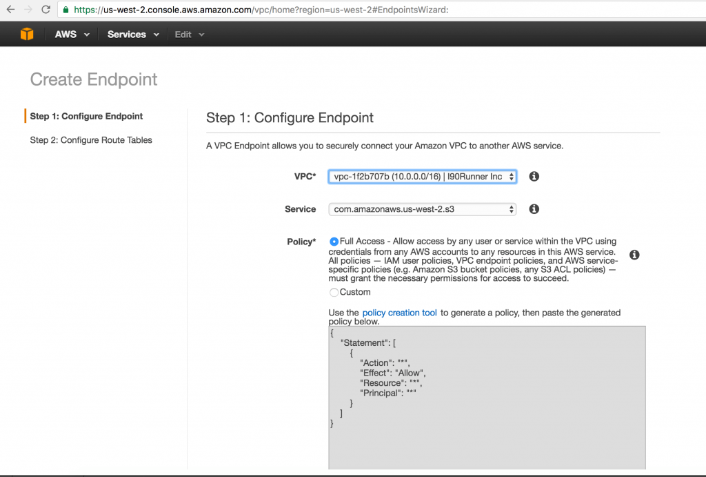
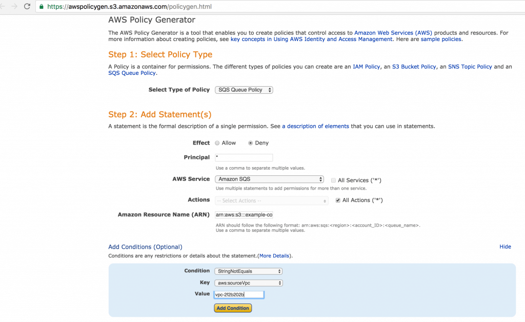
Currently I am evaluating options to lockdown permissions to my S3 Buckets as part of Security Enhancements. These are the steps I followed to lock down S3 Bucket access only to my VPC
Here is a look at some of the common queries that will be useful when troubleshooting AURORA database.
Number of Connections by Host
SELECT SUBSTRING(HOST, 1, 10) , DB,USER , COUNT(*) AS Count
    FROM information_schema.processlist
    group by SUBSTRING(HOST, 0, 10) , DB,USER
    ORDER BY Count desc ;
    -- '10.10.50.22', 'Portal', 'webguest-dev', '46'
Aurora Max Connections
 select AURORA_VERSION();
        select * from mysql.slow_log
        where sql_text not like '%LOAD DATA%'
        order by query_time desc
        limit 1000 ;

        select count(*) from mysql.general_log
        where user_host not like 'rdsadmin%'
        and user_host not like '[rdsadmin]%'
        and event_time > '2017-06-15 18:51:14';

        select current_timestamp();

        desc mysql.general_log  ;

        select @@MAX_CONNECTIONS
        -- '4000'

        select *  from mysql.general_log
        where command_type like '%Connect%';

        select *  from mysql.general_log_backup
        where command_type like '%Connect%' ;

        SHOW GLOBAL STATUS LIKE '%Connection_errors%';

        SHOW STATUS WHERE `variable_name` = 'Threads_connected';
Memory-optimized tables are fully durable by default, and, like transactions on (traditional) disk-based tables, transactions on memory-optimized tables are fully atomic, consistent, isolated, and durable (ACID). Memory-optimized tables and natively compiled stored procedures support only a subset of Transact-SQL features. The following blog post shows how to monitor the table space usage.
                ;
        WITH    system_allocated_memory ( system_allocated_memory_in_mb )
              AS ( SELECT   ISNULL(( SELECT CONVERT(DECIMAL(18, 2),
             ( SUM(TMS.memory_allocated_for_table_kb)
             + SUM(TMS.memory_allocated_for_indexes_kb) )
             / 1024.00)
             FROM   [sys].[dm_db_xtp_table_memory_stats] TMS
             WHERE  TMS.object_id <= 0
             ), 0.00)
         ),
             table_index_memory ( table_used_memory_in_mb, table_unused_memory_in_mb,
             index_used_memory_in_mb, index_unused_memory_in_mb )
             AS ( SELECT   ISNULL(( SELECT CONVERT(DECIMAL(18, 2),
             ( SUM(TMS.memory_used_by_table_kb)
             / 1024.00 ))
             ), 0.00) AS table_used_memory_in_mb ,
             ISNULL(( SELECT CONVERT(DECIMAL(18, 2), ( SUM(TMS.memory_allocated_for_table_kb)
             - SUM(TMS.memory_used_by_table_kb) )
             / 1024.00)
             ), 0.00) AS table_unused_memory_in_mb ,
             ISNULL(( SELECT CONVERT(DECIMAL(18, 2), ( SUM(TMS.memory_used_by_indexes_kb)
             / 1024.00 ))
             ), 0.00) AS index_used_memory_in_mb ,
             ISNULL(( SELECT CONVERT(DECIMAL(18, 2), ( SUM(TMS.memory_allocated_for_indexes_kb)
             - SUM(TMS.memory_used_by_indexes_kb) )
             / 1024.00)
             ), 0.00) AS index_unused_memory_in_mb
             FROM     [sys].[dm_db_xtp_table_memory_stats] TMS
            WHERE    TMS.object_id > 0
           )
        SELECT  s.system_allocated_memory_in_mb ,
                t.table_used_memory_in_mb ,
                t.table_unused_memory_in_mb ,
                t.index_used_memory_in_mb ,
                t.index_unused_memory_in_mb ,
            ISNULL(( SELECT DATABASEPROPERTYEX(DB_NAME(DB_ID()),
            'IsXTPSupported')
            ), 0) AS has_memory_optimized_filegroup
        FROM    system_allocated_memory s ,
           table_index_memory t

        SELECT  t.object_id ,
            t.name ,
            ISNULL(( SELECT CONVERT(DECIMAL(18, 2), ( TMS.memory_used_by_table_kb )
            / 1024.00)
            ), 0.00) AS table_used_memory_in_mb ,
                ISNULL(( SELECT CONVERT(DECIMAL(18, 2), ( TMS.memory_allocated_for_table_kb
                    - TMS.memory_used_by_table_kb )
            / 1024.00)
            ), 0.00) AS table_unused_memory_in_mb ,
                ISNULL(( SELECT CONVERT(DECIMAL(18, 2), ( TMS.memory_used_by_indexes_kb )
            / 1024.00)
            ), 0.00) AS index_used_memory_in_mb ,
                ISNULL(( SELECT CONVERT(DECIMAL(18, 2), ( TMS.memory_allocated_for_indexes_kb
                    - TMS.memory_used_by_indexes_kb )
            / 1024.00)
            ), 0.00) AS index_unused_memory_in_mb
        FROM    sys.tables t
            JOIN sys.dm_db_xtp_table_memory_stats TMS ON ( t.object_id = TMS.object_id )
All Memory Used by Memory Optimized Table across Database Engine
        -- this DMV accounts for all memory used by the hek_2 engine
        SELECT type ,
        name ,
        memory_node_id ,
        pages_kb / 1024 AS pages_MB
        FROM sys.dm_os_memory_clerks
        WHERE type LIKE '%xtp%'
        EXEC [sys].[sp_xtp_control_proc_exec_stats] @new_collection_value = 1
        DECLARE @c BIT
        EXEC sp_xtp_control_proc_exec_stats @old_collection_value = @c OUTPUT
        SELECT  @c AS 'collection status'
DBCC FREEPROCCACHE does not remove natively compiled stored procedures from Plan Cache
                -- https://connect.microsoft.com/SQLServer/Feedback/Details/3126441

        DECLARE @sql NVARCHAR(MAX) = N''

        SELECT  @sql += N'EXECUTE sp_recompile N'''
                + QUOTENAME(SCHEMA_NAME(o.schema_id)) + N'.' + QUOTENAME(o.name) + '''
        '
        FROM    sys.sql_modules sm
                JOIN sys.objects o ON sm.object_id = o.object_id
        WHERE   uses_native_compilation = 1

        EXECUTE sp_executesql @sql


        -- Reset wait and latch statistics.
        DBCC SQLPERF('sys.dm_os_latch_stats' , CLEAR)
        DBCC SQLPERF('sys.dm_os_wait_stats' , CLEAR)
Errors Encountered During Migration :
Msg 41317, Level 16, State 5, Line 6 A user transaction that accesses memory optimized tables or natively compiled modules cannot access more than one user database or databases model and msdb, and it cannot write to master.
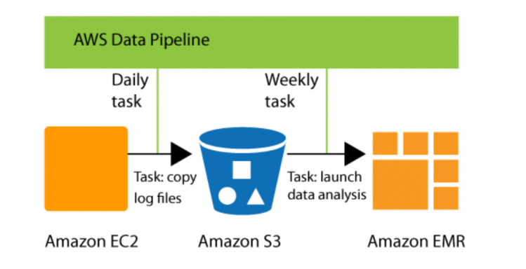
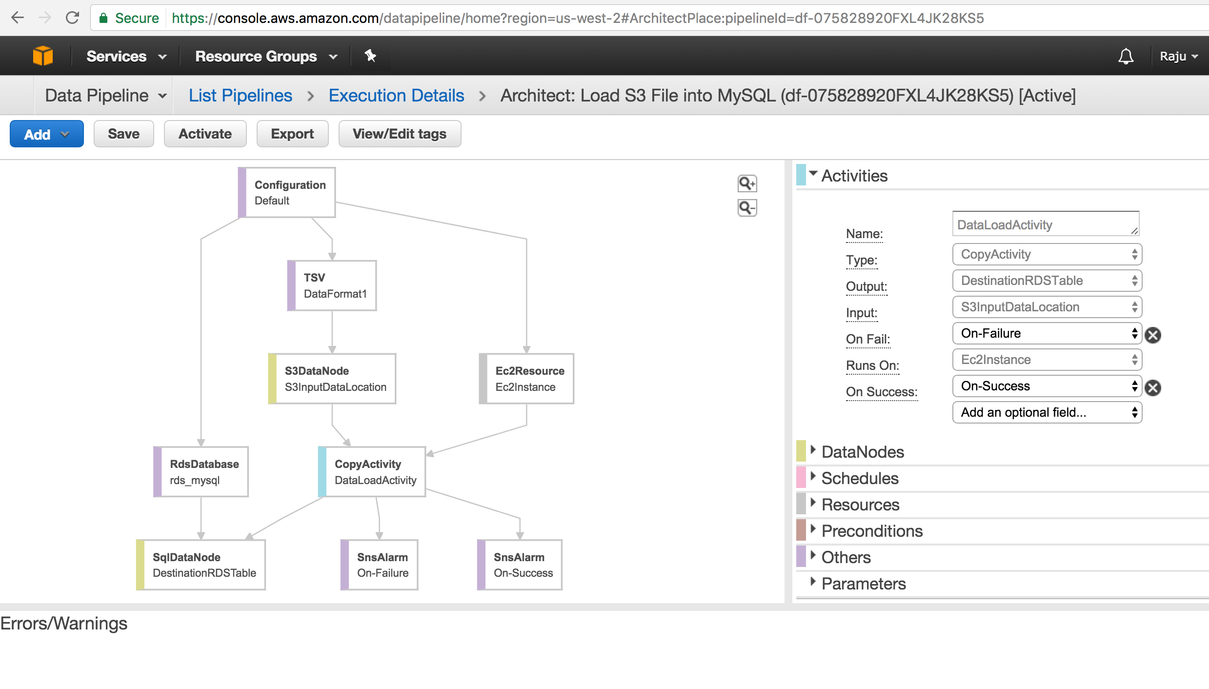
AWS Data Pipeline is a web service that you can use to automate the movement and transformation of data. With AWS Data Pipeline, you can define data-driven workflows, so that tasks can be dependent on the successful completion of previous tasks.
AWS Data Pipe Line Sample Workflow
Default IAM Roles
AWS Data Pipeline requires IAM roles to determine what actions your pipelines can perform and who can access your pipeline’s resources.
The AWS Data Pipeline console creates the following roles for you:
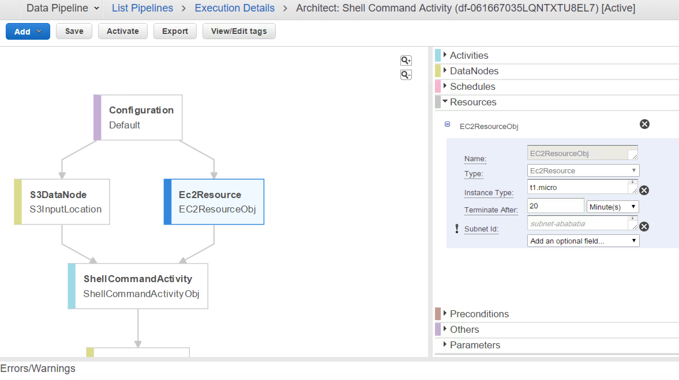
Error MessageUnable to create resource for @EC2ResourceObj_2017-05-05T04:25:32 due to: No default VPC for this user (Service: AmazonEC2; Status Code: 400; Error Code: VPCIdNotSpecified; Request ID: bd2f3abb-d1c9-4c60-977f-6a83426a947d)
Resolution:
When you look at your VPC, you would notice Default VPC is not configured. While launching EC2 Instance on Data Pipeline, by default it can’t figure out which VPC to use and that needs to be explicitly specified in Configurations.
SubNetID for EC2 Resource
Default VaPC
Build Sample Data Pipeline to Load S3 File into MySQL Table :
Use Cases for AWS Data Pipeline Setup sample Pipeline in our develop environment Import Text file from AWS S3 Bucket to AURORA Instance Send out notifications through SNS to [email protected] Export / Import Data Pipe Line Definition.
Prerequisites:
Have MySQL Instance Access to Invoke Data Pipeline with appropriate permissions Target Database and Target Table SNS Notification setup with right configuration
Steps to Follow:
Create Data Pipeline with Name Create MySQL Schema and Table Configure Your EC2 Resource ( Make sure EC2 instance has access to MySQL Instance ). If MySQL instance allows only certain IPS’s and VPC, then you need to configure your EC2 Resource in the same VPC or Subnet. Configure Data Source and appropriate Data Format ( Notice this is Pipe Delimited File ant CSV File ). Configure your SQL Insert Statement Configure SNS Notification for PASS / FAIL Activity. Run your Pipeline and Troubleshoot if errors occur.
You can use “TSV” type as your custom format type and provide:
“Column separator” as pipe(|),
“Record separator” as new line(\n),
“Escape Char” as backslash(\) or any other character you wa
errorId : ActivityFailed:SQLException errorMessage : No value specified for parameter errorMessage : Parameter index out of range (1 > number of parameters, which is 0). errorMessage : Incorrect integer value: ‘FALSE’ for column ‘likesports’ at row 1
Ensure the Table Column Data Type set to correct . By Default MySQL Doesn’t covert TRUE / FALSE into Boolean Data Type.
errorMessage : Parameter index out of range (1 > number of parameters, which is 0). errorMessage for Load script: ERROR 1227 (42000) at line 1: Access denied; you need (at least one of) the LOAD FROM S3 privilege(s) for this operation
This blog post explains how to setup and configure SQL Server docker container on a linux machine. Microsoft recently started supporting running SQL Server on Linux and the entire process takes only few steps to run.
Install SQL Server Docker Image
//Pull the SQL Server Image from the docker registry
$docker pull microsoft/mssql-server-linux
$docker run -e 'ACCEPT_EULA=Y' -e 'SA_PASSWORD=Password' -p 1433:1433 -d microsoft/mssql-server-linux
$docker exec -it 40dd "bash"
$/opt/mssql-tools/bin/sqlcmd -S localhost -U SA
Password:
[root@ip-10-0-0-110 ec2-user]# docker pull microsoft/mssql-server-linux
[root@ip-10-0-0-110 ec2-user]# docker run -e 'ACCEPT_EULA=Y' -e 'SA_PASSWORD=Password' -p 1433:1433 -d microsoft/mssql-server-linux
[root@ip-10-0-0-120 ec2-user]# docker exec -it 40dd "bash"
root@40dde973f4a0:/# /opt/mssql-tools/bin/sqlcmd -S localhost -U SA
Password:

Command History
[root@ip-10-0-0-110 ec2-user]# docker pull microsoft/mssql-server-linux
Using default tag: latest
latest: Pulling from microsoft/mssql-server-linux
4c0c60131530: Pull complete
Digest: sha256:604d27fe5d3d9b4434fb1657e9bf4f2c2bf55ea9bd29dc0cb3660d84bc6f56a8
Status: Downloaded newer image for microsoft/mssql-server-linux:latest
[root@ip-10-0-0-110 ec2-user]# docker run -e 'ACCEPT_EULA=Y' -e 'SA_PASSWORD=Password' -p 1433:1433 -d microsoft/mssql-server-linux
40dde973f4a0cc2af469f9d1c2182403d1e22e28c2a8821e29ce832529965513
[root@ip-10-0-0-120 ec2-user]# docker -it 40dd "bash"
flag provided but not defined: -it
See 'docker --help'.
[root@ip-10-0-0-120 ec2-user]# docker exec -it 40dd "bash"
root@40dde973f4a0:/# /opt/mssql-tools/bin/sqlcmd -S localhost -U SA
Password:
1> select @@servername;
2> go

--------------------------------------------------------------------------------------------------------------------------------
40dde973f4a0

(1 rows affected)
1> select db_name();
2> go

--------------------------------------------------------------------------------------------------------------------------------
master

(1 rows affected)
Version Info:
select @@version

/*
Microsoft SQL Server 2017 (CTP2.1) - 14.0.600.250 (X64)
May 10 2017 12:21:23
Copyright (C) 2017 Microsoft Corporation. All rights reserved.
Developer Edition (64-bit) on Linux (Ubuntu 16.04.2 LTS)
*/
Backup Database on Docker Container and Copy to Host:
Connect to SQL Server Management Studio or SQLCMD and issue the backup command
Backup Database on Docker Container
BACKUP DATABASE H1BData_V2
TO DISK ='/var/opt/mssql/data/SalaryDatabase_V2_06132017.bak'
Copy the file from Container to Host and Sync with S3 Bucket:
root@e83b4048db28:/var/opt/mssql/log# /opt/mssql-tools/bin/sqlcmd -S localhost -U SA
Password:
Sqlcmd: Error: Microsoft ODBC Driver 13 for SQL Server : Login failed for user ‘SA’..
root@e83b4048db28:/var/opt/mssql/log# exit
exit
[root@ip-10-0-0-120 ec2-user]# docker rm $(docker ps -a -q)
Error response from daemon: You cannot remove a running container e83b4048db28505951f20fff4aff9f5132695fd1e1c7251c8daeb79d15ac403d. Stop the container before attempting removal or use -f
[root@ip-10-0-0-120 ec2-user]# docker rm -f $(docker ps -a -q)
e83b4048db28
Unable to telnet without allowing access to port 1433
MacBook:.ssh Raju$ telnet 54.44.40.26 1433
Trying 54.44.40.26…
telnet: connect to address 54.44.40.26: Operation timed out
telnet: Unable to connect to remote host
MacBook:.ssh Raju$ telnet 54.44.40.26 1433
Trying 54.44.40.26…
Connected to ec2-54-44-40-26.us-west-2.compute.amazonaws.com.
Escape character is ‘^]’.
^CError while connecting through SQL Server Management Studio without allowing access to port 1433
TITLE: Connect to Server
——————————
Cannot connect to 54.44.40.26.
——————————
ADDITIONAL INFORMATION:
A network-related or instance-specific error occurred while establishing a connection to SQL Server. The server was not found or was not accessible. Verify that the instance name is correct and that SQL Server is configured to allow remote connections. (provider: Named Pipes Provider, error: 40 – Could not open a connection to SQL Server) (Microsoft SQL Server, Error: 53)
Error while connecting through SQLCMD without allowing access to port 1433

C:\Users\>sqlcmd -S 54.44.40.26 -U SA
Password: HResult 0x35, Level 16, State 1
Named Pipes Provider: Could not open a connection to SQL Server [53].
Sqlcmd: Error: Microsoft SQL Server Native Client 10.0 : A network-related or in
stance-specific error has occurred while establishing a connection to SQL Server
. Server is not found or not accessible. Check if instance name is correct and i
f SQL Server is configured to allow remote connections. For more information see
SQL Server Books Online..
Sqlcmd: Error: Microsoft SQL Server Native Client 10.0 : Login timeout expired.
Open port 1433 in Security Groups
Allow inbound traffic from the IP’s or Security Groups you need SQL Server Access.
017-06-09 00:08:39.35 spid9s Starting up database ‘tempdb’.
2017-06-09 00:08:39.45 spid26s Recovery of database ‘UserDBName’ (7) is 0% complete (approximately 1717 seconds remain). Phase 2 of 3. This is an informational message only. No user action is required.
2017-06-09 00:08:40.15 spid9s The tempdb database has 1 data file(s).
2017-06-09 00:08:40.16 spid36s The Service Broker endpoint is in disabled or stopped state.
2017-06-09 00:08:40.17 spid36s The Database Mirroring endpoint is in disabled or stopped state.
2017-06-09 00:08:40.35 spid36s Service Broker manager has started.
2017-06-09 00:08:41.05 spid33s [INFO] HkRecoverFromLogOpenRange(): Database ID: [5]. Log recovery scan from 00000495:00005D20:006B to 000004C7:00010F48:0002.
2017-06-09 00:08:59.47 spid26s Recovery of database ‘UserDBName’ (7) is 16% complete (approximately 110 seconds remain). Phase 2 of 3. This is an informational message only. No user action is required.
2017-06-09 00:09:11.16 Logon Error: 18456, Severity: 14, State: 38.
2017-06-09 00:09:11.16 Logon Login failed for user ‘UserName’. Reason: Failed to open the explicitly specified database ‘UserDBName’. [CLIENT: 00.000.00.00]
2017-06-09 00:09:19.51 spid26s Recovery of database ‘UserDBName’ (7) is 30% complete (approximately 94 seconds remain). Phase 2 of 3. This is an informational message only. No user action is required.
2017-06-09 00:09:39.59 spid26s Recovery of database ‘UserDBName’ (7) is 44% complete (approximately 76 seconds remain). Phase 2 of 3. This is an informational message only. No user action is required.
2017-06-09 00:09:51.38 spid26s Recovery of database ‘UserDBName’ (7) is 54% complete (approximately 62 seconds remain). Phase 2 of 3. This is an informational message only. No user action is required.
2017-06-09 00:09:51.40 spid26s Recovery of database ‘UserDBName’ (7) is 54% complete (approximately 62 seconds remain). Phase 3 of 3. This is an informational message only. No user action is required.
DBSTARTUP (UserDBName, 7): FCBOpenTime took 164 ms
DBSTARTUP (UserDBName, 7): FCBHeaderReadTime took 135 ms
DBSTARTUP (UserDBName, 7): FileMgrPreRecoveryTime took 277 ms
DBSTARTUP (UserDBName, 7): MasterFilesScanTime took 144 ms
DBSTARTUP (UserDBName, 7): AnalysisRecTime took 1470 ms
DBSTARTUP (UserDBName, 7): RedoRecTime took 71938 ms
DBSTARTUP (UserDBName, 7): UndoRecTime took 4903 ms
DBSTARTUP (UserDBName, 7): PhysicalRecoveryTime took 73408 ms
DBSTARTUP (UserDBName, 7): PhysicalCompletionTime took 4913 ms
DBSTARTUP (UserDBName, 7): RecoveryCompletionTime took 102 ms
DBSTARTUP (UserDBName, 7): StartupInDatabaseTime took 136 ms
DBSTARTUP (UserDBName, 7): RemapSysfiles1Time took 125 ms
2017-06-09 00:10:11.44 spid6s Recovery of database ‘UserDBName’ (7) is 63% complete (approximately 55 seconds remain). Phase 3 of 3. This is an informational message only. No user action is required.
2017-06-09 00:10:31.48 spid6s Recovery of database ‘UserDBName’ (7) is 63% complete (approximately 65 seconds remain). Phase 3 of 3. This is an informational message only. No user action is required.
2017-06-09 00:10:34.61 spid33s [INFO] HkRedoCloseLastOpenRangeSegment(): Database ID: [5]. Log recovery open segment scan from 00000495:00005D20:006B to 000004C7:00010E78:002F.
2017-06-09 00:10:34.67 spid25s [INFO] redoOpenRangeSegment(): Database ID: [5]. Log recovery open segment scan completed at 000004C7:00010E78:002F.
2017-06-09 00:10:34.67 spid25s [INFO] HkPrintUndoRowStats(): Database ID: [5]. Undo Rows Stats. [UndoRowsSeen] = 0, [UndoRowsMatched] = 0, [InsertRowsMatched] = 0, [InsertRowsSeen] = 0, [UndoRowsAborted] = 0
DBSTARTUP (UserDBName, 5): FCBOpenTime took 202 ms
DBSTARTUP (UserDBName, 5): FCBHeaderReadTime took 133 ms
DBSTARTUP (UserDBName, 5): FileMgrPreRecoveryTime took 308 ms
DBSTARTUP (UserDBName, 5): MasterFilesScanTime took 158 ms
DBSTARTUP (UserDBName, 5): StreamFileMgrPreRecoveryTime took 141 ms
DBSTARTUP (UserDBName, 5): LogMgrPreRecoveryTime took 478 ms
DBSTARTUP (UserDBName, 5): PhysicalCompletionTime took 116181 ms
DBSTARTUP (UserDBName, 5): HekatonRecoveryTime took 116167 ms
2017-06-09 00:10:34.84 spid24s Recovery completed for database UserDBName (database ID 5) in 117 second(s) (analysis 12 ms, redo 0 ms, undo 50 ms.) This is an informational message only. No user action is required.
2017-06-09 00:10:51.48 spid6s Recovery of database ‘UserDBName’ (7) is 71% complete (approximately 53 seconds remain). Phase 3 of 3. This is an informational message only. No user action is required.
2017-06-09 00:11:11.54 spid6s Recovery of database ‘UserDBName’ (7) is 99% complete (approximately 1 seconds remain). Phase 3 of 3. This is an informational message only. No user action is required.
2017-06-09 00:11:11.54 spid6s 23 transactions rolled back in database ‘UserDBName’ (7:0). This is an informational message only. No user action is required.
2017-06-09 00:11:11.55 spid6s Recovery is writing a checkpoint in database ‘UserDBName’ (7). This is an informational message only. No user action is required.
2017-06-09 00:11:11.55 spid6s Recovery completed for database UserDBName (database ID 7) in 154 second(s) (analysis 1405 ms, redo 71933 ms, undo 80147 ms.) This is an informational message only. No user action is required.
2017-06-09 00:11:11.56 spid6s Parallel redo is shutdown for database ‘UserDBName’ with worker pool size [2].
2017-06-09 00:11:11.57 spid6s Recovery is complete. This is an informational message only. No user action is required.

Errors while reading log file
EXEC sp_readerrorlog

Msg 22004, Level 16, State 1, Line 0
The log file is not using Unicode format.
===================================
The log file is not using Unicode format. (.Net SqlClient Data Provider)
——————————
For help, click: http://go.microsoft.com/fwlink?ProdName=Microsoft%20SQL%20Server&ProdVer=14.00.0600&EvtSrc=MSSQLServer&EvtID=22004&LinkId=20476
——————————
Server Name: 52.42.36.22
Error Number: 22004
Severity: 16
State: 1
Running out of Space
Msg 3202, Level 16, State 1, Line 5 Write on “/var/opt/mssql/data/HWageInfo_06132017.bak” failed: Insufficient bytes transferred. Common causes are backup configuration, insufficient disk space, or other problems with the storage subsystem such as corruption or hardware failure. Check errorlogs/application-logs for detailed messages and correct error conditions. Msg 3013, Level 16, State 1, Line 5 BACKUP DATABASE is terminating abnormally. Ensure you have enough disk space. Ensure you have enough disk space.
Our goal is to identify whether Amazon SQL Server RDS Service provides elastic , highly available , Scalable and operationally efficient solution for our use case. We are evaluating options to migrate our read/write heavy production SQL Server database to amazon SQL Server RDS. We have pretty high throughput needs for few hours a day for few months in a year ,which is mission critical for our business success. Any downtown during peak usuage would be catastrophic for our business. We are evaluating pros and cons of moving to amazon RDS with provisioned IOPS.
Caveats of AWS RDS SQL Server:
These information we gathered while working with SQL Server RDS.
Feature Name
Yes/No
Description
SQL Server 2016 Support
No
Microsoft says SQL Server 2016 comes with very rich feature set and ton on OLTP Enhancements
Native Backup Restore
Yes
AWS RDS Released this feature a week ago , which makes moving databases across environments lot more easier.
Elastic IOPS
No
Storage and IOPS needs to be incremented linearly for higher performance. You can’t get higher IOPS without increasing storage.
Elastic Storage
No
Scaling Storage is not an option after launching an instance
RAID Support
No
We usually have RAID 10 for production workload and RDS doesn’t have options to configure RAID
Point in Time Restore on Same Instance
No
You can’t do Point in Time Restore on the existing database. You have to spin up new Instance
AlwaysOn Availability Groups
No
This provides ability to failover group of databases to your secondary instance
Mirroring
Yes
Mirroring is Deprecated feature and its replaced with AlwaysOn Availability Groups
Linked Servers from RDS
No
But Linked Servers to RDS is Allowed.
Service Broker
No
Comes handy for services
No Admin privileges.You can’t execute normal sql server system stored procedures and you need to work with options groupand parameters group to modify configuration. You can’t execute sp_configure to change configurations.
@@@@@@@@@@@@@@@@@@@@@@@@@@@@@@@@@@@@@@@@@@@@@@@@@@@@@@@@@@@
@ WARNING: REMOTE HOST IDENTIFICATION HAS CHANGED! @
@@@@@@@@@@@@@@@@@@@@@@@@@@@@@@@@@@@@@@@@@@@@@@@@@@@@@@@@@@@
IT IS POSSIBLE THAT SOMEONE IS DOING SOMETHING NASTY!
Someone could be eavesdropping on you right now (man-in-the-middle attack)!
It is also possible that a host key has just been changed.
The fingerprint for the RSA key sent by the remote host is
SHA256:oFgx2U4Q0KUxtFnouxHYJdLyH6qDbX/rKtsg
Please contact your system administrator.
Add correct host key in /Users/username/.ssh/known_hosts to get rid of this message.
Offending RSA key in /Users/ username /.ssh/known_hosts:1
RSA host key for 54.214.1.26 has changed and you have requested strict checking.
Host key verification failed.
Edit known_hosts and remove the offending host entry and SSH into Host Again
username -MBP:.ssh username $ vi known_hosts
username -MBP:.ssh username $ ssh -i Key.pem [email protected]
The authenticity of host ‘54.214.1.26 (54.214.1.26)’ can’t be established.
ECDSA key fingerprint is SHA256:2VcR+DiKNRwyQwZ2LqtZ6EHxQYv5MWMAsrrI.
Are you sure you want to continue connecting (yes/no)? yes
Warning: Permanently added ‘54.214.1.26’ (ECDSA) to the list of known hosts.
Last login: Fri Jul 29 23:08:35 2016 from
__| __|_ )
_| ( / Amazon Linux AMI
___|\___|___|
https://aws.amazon.com/amazon-linux-ami/2016.03-release-notes/
4 package(s) needed for security, out of 4 available
Run “sudo yum update” to apply all updates.
CloudIQ is a leading Cloud Consulting and Solutions firm that helps businesses solve today’s problems and plan the enterprise of tomorrow by integrating intelligent cloud solutions. We help you leverage the technologies that make your people more productive, your infrastructure more intelligent, and your business more profitable.